


TMS320F2809, TMS320F2808, TMS320F2806
TMS320F2802, TMS320F2801, TMS320C2802
TMS320C2801, TMS320F28016, TMS320F28015
www.ti.com
SPRS230L–OCTOBER 2003–REVISED DECEMBER 2009
6.4.1 Reducing Current Consumption
280x devices have a richer peripheral mix compared to the 281x family. While the McBSP has been
removed, the following new peripherals have been added on the 280x:
• 3 SPI modules
• 1 CAN module
• 1 I2C module
The two event manager modules of the 281x have been enhanced and replaced with separate ePWM (6),
eCAP (4) and eQEP (2) modules, providing tremendous flexibility in applications. Like 281x, 280x DSPs
incorporate a unique method to reduce the device current consumption. Since each peripheral unit has an
individual clock-enable bit, significant reduction in current consumption can be achieved by turning off the
clock to any peripheral module that is not used in a given application. Furthermore, any one of the three
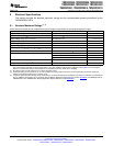
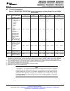
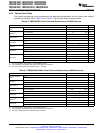
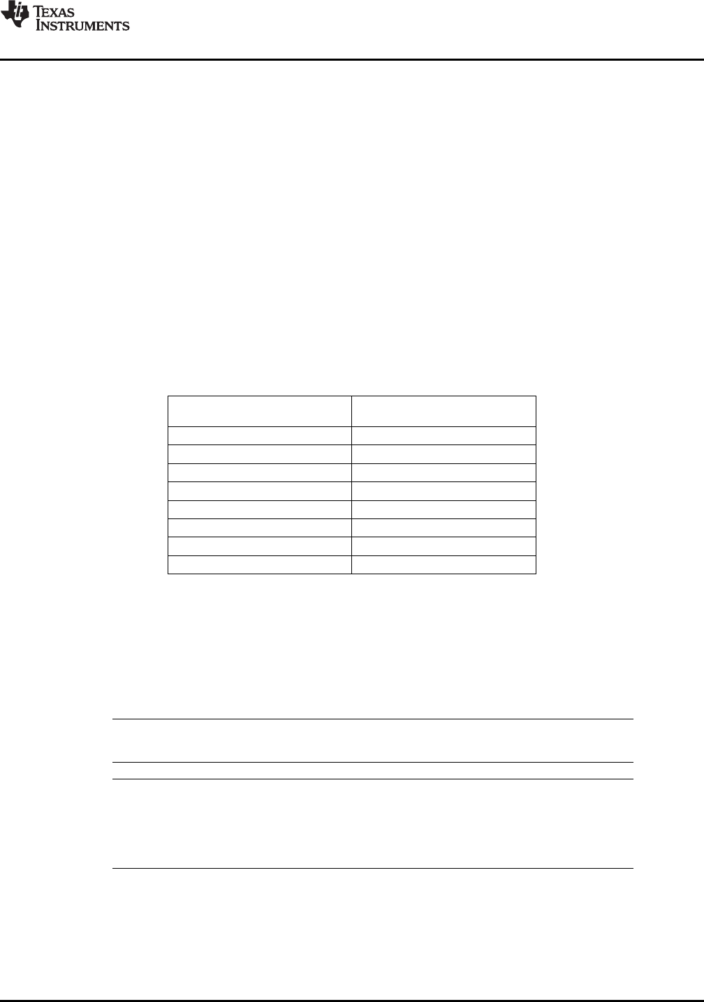
low-power modes could be taken advantage of to reduce the current consumption even further. Table 6-5
indicates the typical reduction in current consumption achieved by turning off the clocks.
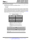
Table 6-5. Typical Current Consumption by Various
Peripherals (at 100 MHz)
(1)
PERIPHERAL I
DD
CURRENT
MODULE REDUCTION (mA)
(2)
ADC 8
(3)
I2C 5
eQEP 5
ePWM 5
eCAP 2
SCI 4
SPI 5
eCAN 11
(1) All peripheral clocks are disabled upon reset. Writing to/reading from
peripheral registers is possible only after the peripheral clocks are
turned on.
(2) For peripherals with multiple instances, the current quoted is per
module. For example, the 5 mA number quoted for ePWM is for one
ePWM module.
(3) This number represents the current drawn by the digital portion of
the ADC module. Turning off the clock to the ADC module results in
the elimination of the current drawn by the analog portion of the ADC
(I
DDA18
) as well.
NOTE
I
DDIO
current consumption is reduced by 15 mA (typical) when XCLKOUT is turned off.
NOTE
The baseline I
DD
current (current when the core is executing a dummy loop with no
peripherals enabled) is 110 mA, typical. To arrive at the I
DD
current for a given application,
the current-drawn by the peripherals (enabled by that application) must be added to the
baseline I
DD
current.
Copyright © 2003–2009, Texas Instruments Incorporated Electrical Specifications 99
Submit Documentation Feedback
Product Folder Link(s): TMS320F2809 TMS320F2808 TMS320F2806 TMS320F2802 TMS320F2801 TMS320C2802
TMS320C2801 TMS320F28016 TMS320F28015