


TMS320F2809, TMS320F2808, TMS320F2806
TMS320F2802, TMS320F2801, TMS320C2802
TMS320C2801, TMS320F28016, TMS320F28015
SPRS230L–OCTOBER 2003–REVISED DECEMBER 2009
www.ti.com
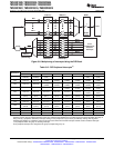
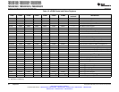
3.7 Low-Power Modes Block
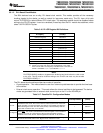
The low-power modes on the 280x are similar to the 240x devices. Table 3-18 summarizes the various
modes.
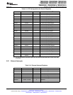
Table 3-18. Low-Power Modes
MODE LPMCR0(1:0) OSCCLK CLKIN SYSCLKOUT EXIT
(1)
XRS, Watchdog interrupt, any enabled
IDLE 00 On On On
(2)
interrupt, XNMI
On XRS, Watchdog interrupt, GPIO Port A
STANDBY 01 Off Off
(watchdog still running) signal, debugger
(3)
, XNMI
Off
XRS, GPIO Port A signal, XNMI,
HALT 1X (oscillator and PLL turned off, Off Off
debugger
(3)
watchdog not functional)
(1) The Exit column lists which signals or under what conditions the low power mode will be exited. A low signal, on any of the signals, will
exit the low power condition. This signal must be kept low long enough for an interrupt to be recognized by the device. Otherwise the
IDLE mode will not be exited and the device will go back into the indicated low power mode.
(2) The IDLE mode on the C28x behaves differently than on the 24x/240x. On the C28x, the clock output from the CPU (SYSCLKOUT) is
still functional while on the 24x/240x the clock is turned off.
(3) On the C28x, the JTAG port can still function even if the CPU clock (CLKIN) is turned off.
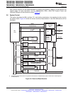
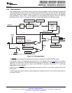
The various low-power modes operate as follows:
IDLE Mode: This mode is exited by any enabled interrupt or an XNMI that is recognized
by the processor. The LPM block performs no tasks during this mode as
long as the LPMCR0(LPM) bits are set to 0,0.
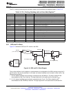
STANDBY Mode: Any GPIO port A signal (GPIO[31:0]) can wake the device from STANDBY
mode. The user must select which signal(s) will wake the device in the
GPIOLPMSEL register. The selected signal(s) are also qualified by the
OSCCLK before waking the device. The number of OSCCLKs is specified in
the LPMCR0 register.
HALT Mode: Only the XRS and any GPIO port A signal (GPIO[31:0]) can wake the
device from HALT mode. The user selects the signal in the GPIOLPMSEL
register.
NOTE
The low-power modes do not affect the state of the output pins (PWM pins included).
They will be in whatever state the code left them in when the IDLE instruction was
executed. See the TMS320x280x, 2801x, 2804x DSP System Control and Interrupts
Reference Guide (literature number SPRU712) for more details.
52 Functional Overview Copyright © 2003–2009, Texas Instruments Incorporated
Submit Documentation Feedback
Product Folder Link(s): TMS320F2809 TMS320F2808 TMS320F2806 TMS320F2802 TMS320F2801 TMS320C2802
TMS320C2801 TMS320F28016 TMS320F28015