


TMS320F2809, TMS320F2808, TMS320F2806
TMS320F2802, TMS320F2801, TMS320C2802
TMS320C2801, TMS320F28016, TMS320F28015
SPRS230L–OCTOBER 2003–REVISED DECEMBER 2009
www.ti.com
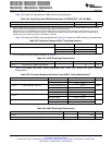
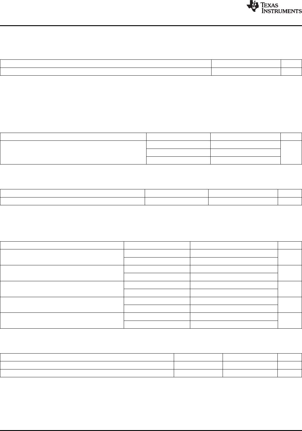
Table 6-25 shows the high-resolution PWM switching characteristics.
Table 6-25. High-Resolution PWM Characteristics at SYSCLKOUT = (60–100 MHz)
MIN TYP MAX UNIT
Micro Edge Positioning (MEP) step size
(1)
150 310 ps
(1) Maximum MEP step size is based on worst-case process, maximum temperature and maximum voltage. MEP step size will increase
with low voltage and high temperature and decrease with voltage and cold temperature.
Applications that use the HRPWM feature should use MEP Scale Factor Optimizer (SFO) estimation software functions. See the TI
software libraries for details of using SFO function in end applications. SFO functions help to estimate the number of MEP steps per
SYSCLKOUT period dynamically while the HRPWM is in operation.
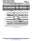
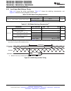
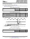
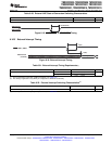
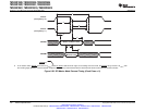
Table 6-26 shows the eCAP timing requirement and Table 6-27 shows the eCAP switching characteristics.
Table 6-26. Enhanced Capture (eCAP) Timing Requirement
(1)
TEST CONDITIONS MIN MAX UNIT
t
w(CAP)
Capture input pulse width Asynchronous 2t
c(SCO)
cycles
Synchronous 2t
c(SCO)
With input qualifier 1t
c(SCO)
+ t
w(IQSW)
(1) For an explanation of the input qualifier parameters, see Table 6-15 .
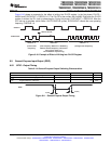
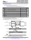
Table 6-27. eCAP Switching Characteristics
PARAMETER TEST CONDITIONS MIN MAX UNIT
t
w(APWM)
Pulse duration, APWMx output high/low 20 ns
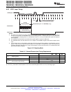
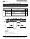
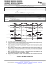
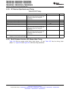
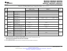
Table 6-28 shows the eQEP timing requirement and Table 6-29 shows the eQEP switching
characteristics.
Table 6-28. Enhanced Quadrature Encoder Pulse (eQEP) Timing Requirements
(1)
TEST CONDITIONS MIN MAX UNIT
t
w(QEPP)
QEP input period Asynchronous/synchronous 2t
c(SCO)
cycles
With input qualifier 2[1t
c(SCO)
+ t
w(IQSW)
]
t
w(INDEXH)
QEP Index Input High time Asynchronous/synchronous 2t
c(SCO)
cycles
With input qualifier 2t
c(SCO)
+t
w(IQSW)
t
w(INDEXL)
QEP Index Input Low time Asynchronous/synchronous 2t
c(SCO)
cycles
With input qualifier 2t
c(SCO)
+ t
w(IQSW)
t
w(STROBH)
QEP Strobe High time Asynchronous/synchronous 2t
c(SCO)
cycles
With input qualifier 2t
c(SCO)
+ t
w(IQSW)
t
w(STROBL)
QEP Strobe Input Low time Asynchronous/synchronous 2t
c(SCO)
cycles
With input qualifier 2t
c(SCO)
+t
w(IQSW)
(1) For an explanation of the input qualifier parameters, see Table 6-15 .
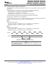
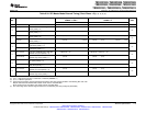
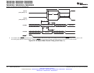
Table 6-29. eQEP Switching Characteristics
PARAMETER TEST CONDITIONS MIN MAX UNIT
t
d(CNTR)xin
Delay time, external clock to counter increment 4t
c(SCO)
cycles
t
d(PCS-OUT)QEP
Delay time, QEP input edge to position compare sync output 6t
c(SCO)
cycles
116 Electrical Specifications Copyright © 2003–2009, Texas Instruments Incorporated
Submit Documentation Feedback
Product Folder Link(s): TMS320F2809 TMS320F2808 TMS320F2806 TMS320F2802 TMS320F2801 TMS320C2802
TMS320C2801 TMS320F28016 TMS320F28015