


C4
C3
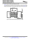
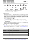
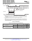
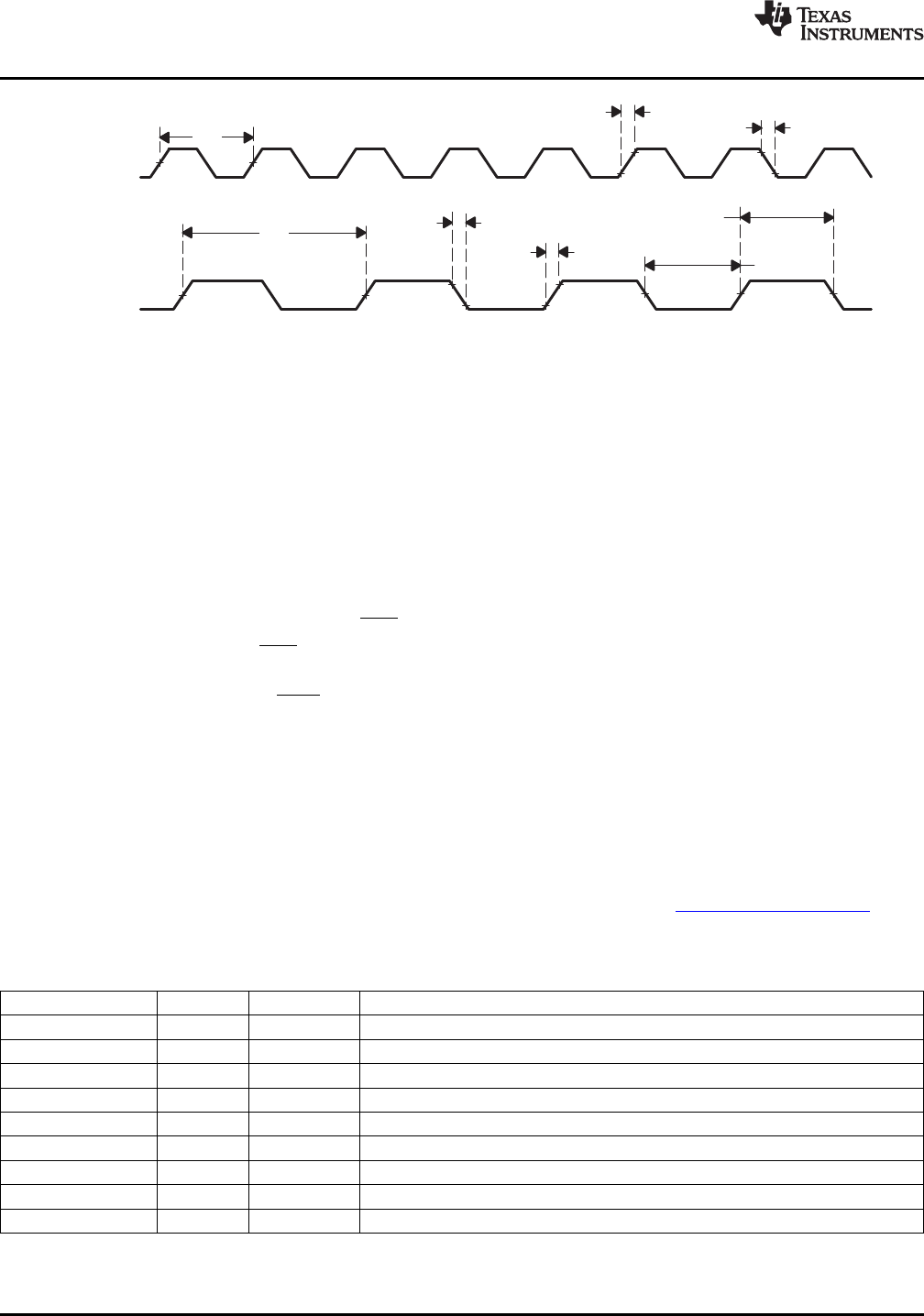
XCLKOUT
(B)
XCLKIN
(A)
C5
C9
C10
C1
C8
C6
TMS320F2809, TMS320F2808, TMS320F2806
TMS320F2802, TMS320F2801, TMS320C2802
TMS320C2801, TMS320F28016, TMS320F28015
SPRS230L–OCTOBER 2003–REVISED DECEMBER 2009
www.ti.com
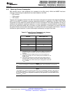
A. The relationship of XCLKIN to XCLKOUT depends on the divide factor chosen. The waveform relationship shown is
intended to illustrate the timing parameters only and may differ based on actual configuration.
B. XCLKOUT configured to reflect SYSCLKOUT.
Figure 6-7. Clock Timing
6.8 Power Sequencing
No requirements are placed on the power up/down sequence of the various power pins to ensure the
correct reset state for all the modules. However, if the 3.3-V transistors in the level shifting output buffers
of the I/O pins are powered prior to the 1.8-V transistors, it is possible for the output buffers to turn on,
causing a glitch to occur on the pin during power up. To avoid this behavior, power the V
DD
(core voltage)
pins prior to or simultaneously with the V
DDIO
(input/output voltage) pins, ensuring that the V
DD
pins have
reached 0.7 V before the V
DDIO
pins reach 0.7 V.
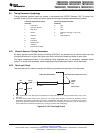
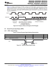
There are some requirements on the XRS pin:
1. During power up, the XRS pin must be held low for t
w(RSL1)
after the input clock is stable (see
Table 6-13). This is to enable the entire device to start from a known condition.
2. During power down, the XRS pin must be pulled low at least 8 μs prior to V
DD
reaching 1.5 V. This is to
enhance flash reliability.
Additionally it is recommended that no voltage larger than a diode drop (0.7 V) should be applied to any
pin prior to powering up the device. Voltages applied to pins on an unpowered device can bias internal p-n
junctions in unintended ways and produce unpredictable results.
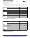
6.8.1 Power Management and Supervisory Circuit Solutions
Table 6-12 lists the power management and supervisory circuit solutions for 280x DSPs. LDO selection
depends on the total power consumed in the end application. Go to http://www.power.ti.com for a
complete list of TI power ICs.
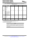
Table 6-12. Power Management and Supervisory Circuit Solutions
SUPPLIER TYPE PART DESCRIPTION
Texas Instruments LDO TPS767D301 Dual 1-A low-dropout regulator (LDO) with supply voltage supervisor (SVS)
Texas Instruments LDO TPS70202 Dual 500/250-mA LDO with SVS
Texas Instruments LDO TPS766xx 250-mA LDO with PG
Texas Instruments SVS TPS3808 Open Drain SVS with programmable delay
Texas Instruments SVS TPS3803 Low-cost Open-drain SVS with 5 μS delay
Texas Instruments LDO TPS799xx 200-mA LDO in WCSP package
Texas Instruments LDO TPS736xx 400-mA LDO with 40 mV of V
DO
Texas Instruments DC/DC TPS62110 High V
in
1.2-A dc/dc converter in 4x4 QFN package
Texas Instruments DC/DC TPS6230x 500-mA converter in WCSP package
106 Electrical Specifications Copyright © 2003–2009, Texas Instruments Incorporated
Submit Documentation Feedback
Product Folder Link(s): TMS320F2809 TMS320F2808 TMS320F2806 TMS320F2802 TMS320F2801 TMS320C2802
TMS320C2801 TMS320F28016 TMS320F28015