


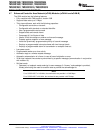
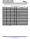
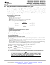

Baud rate =
LSPCLK
16
LSPCLK
(BRR ) 1) * 8
when BRR ≠ 0
Baud rate = when BRR = 0
Max bit rate +
100 MHz
16
+ 6.25 10
6
bńs
Max bit rate +
60 MHz
16
+ 3.75 10
6
bńs
TMS320F2809, TMS320F2808, TMS320F2806
TMS320F2802, TMS320F2801, TMS320C2802
TMS320C2801, TMS320F28016, TMS320F28015
www.ti.com
SPRS230L–OCTOBER 2003–REVISED DECEMBER 2009
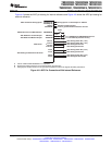
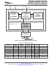
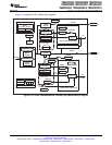
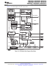
4.8 Serial Communications Interface (SCI) Modules (SCI-A, SCI-B)
The 280x devices include two serial communications interface (SCI) modules. The SCI modules support
digital communications between the CPU and other asynchronous peripherals that use the standard
non-return-to-zero (NRZ) format. The SCI receiver and transmitter are double-buffered, and each has its
own separate enable and interrupt bits. Both can be operated independently or simultaneously in the
full-duplex mode. To ensure data integrity, the SCI checks received data for break detection, parity,
overrun, and framing errors. The bit rate is programmable to over 65000 different speeds through a 16-bit
baud-select register.
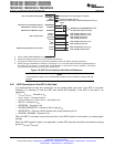
Features of each SCI module include:
• Two external pins:
– SCITXD: SCI transmit-output pin
– SCIRXD: SCI receive-input pin
NOTE: Both pins can be used as GPIO if not used for SCI.
– Baud rate programmable to 64K different rates:
• Data-word format
– One start bit
– Data-word length programmable from one to eight bits
– Optional even/odd/no parity bit
– One or two stop bits
• Four error-detection flags: parity, overrun, framing, and break detection
• Two wake-up multiprocessor modes: idle-line and address bit
• Half- or full-duplex operation
• Double-buffered receive and transmit functions
• Transmitter and receiver operations can be accomplished through interrupt-driven or polled algorithms
with status flags.
– Transmitter: TXRDY flag (transmitter-buffer register is ready to receive another character) and TX
EMPTY flag (transmitter-shift register is empty)
– Receiver: RXRDY flag (receiver-buffer register is ready to receive another character), BRKDT flag
(break condition occurred), and RX ERROR flag (monitoring four interrupt conditions)
• Separate enable bits for transmitter and receiver interrupts (except BRKDT)
• (for 100 MHz devices)
(for 60 MHz devices)
• NRZ (non-return-to-zero) format
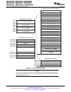
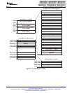
• Ten SCI module control registers located in the control register frame beginning at address 7050h
NOTE
All registers in this module are 8-bit registers that are connected to Peripheral Frame 2.
When a register is accessed, the register data is in the lower byte (7–0), and the upper
byte (15–8) is read as zeros. Writing to the upper byte has no effect.
Copyright © 2003–2009, Texas Instruments Incorporated Peripherals 73
Submit Documentation Feedback
Product Folder Link(s): TMS320F2809 TMS320F2808 TMS320F2806 TMS320F2802 TMS320F2801 TMS320C2802
TMS320C2801 TMS320F28016 TMS320F28015