


WAKE INT
(A)
XCLKOUT
Address/Data
(internal)
t
d(WAKE−IDLE)
t
w(WAKE−INT)
TMS320F2809, TMS320F2808, TMS320F2806
TMS320F2802, TMS320F2801, TMS320C2802
TMS320C2801, TMS320F28016, TMS320F28015
SPRS230L–OCTOBER 2003–REVISED DECEMBER 2009
www.ti.com
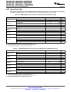
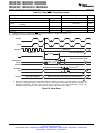
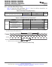
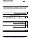
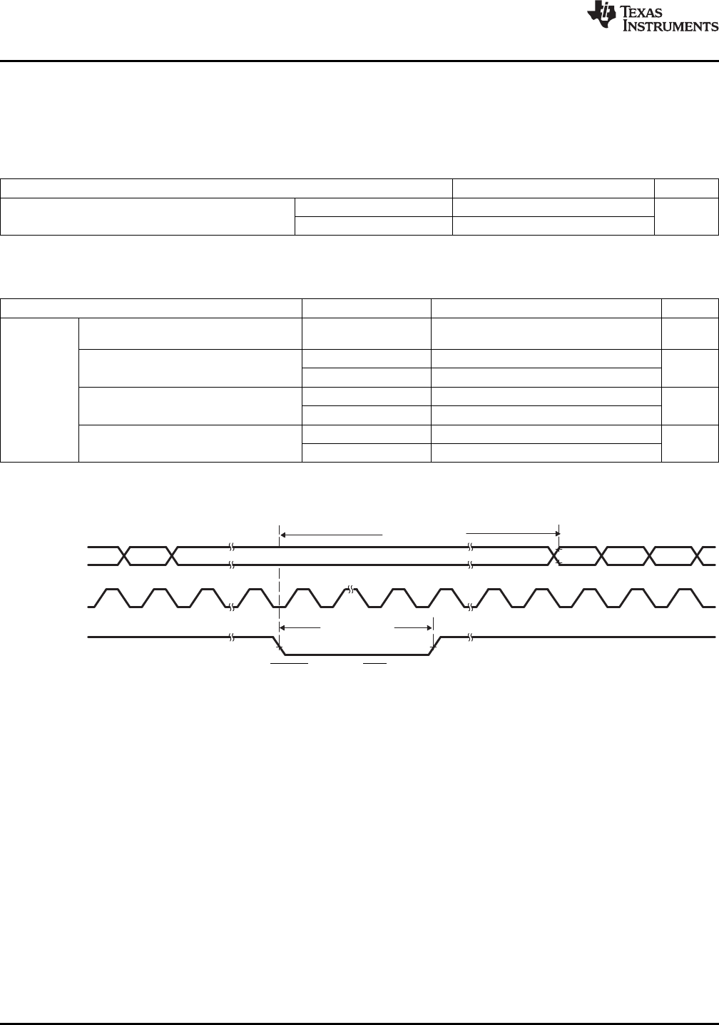
6.9.4 Low-Power Mode Wakeup Timing
Table 6-16 shows the timing requirements, Table 6-17 shows the switching characteristics, and
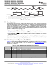
Figure 6-14 shows the timing diagram for IDLE mode.
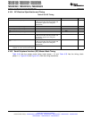
Table 6-16. IDLE Mode Timing Requirements
(1)
MIN NOM MAX UNIT
Without input qualifier 2t
c(SCO)
t
w(WAKE-INT)
Pulse duration, external wake-up signal cycles
With input qualifier 5t
c(SCO)
+ t
w(IQSW)
(1) For an explanation of the input qualifier parameters, see Table 6-15 .
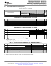
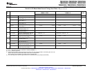
Table 6-17. IDLE Mode Switching Characteristics
(1)
PARAMETER TEST CONDITIONS MIN TYP MAX UNIT
Delay time, external wake signal to
program execution resume
(2)
Without input qualifier 20t
c(SCO)
cycles
• Wake-up from Flash
– Flash module in active state With input qualifier 20t
c(SCO)
+ t
w(IQSW)
t
d(WAKE-IDLE)
Without input qualifier 1050t
c(SCO)
cycles
• Wake-up from Flash
– Flash module in sleep state With input qualifier 1050t
c(SCO)
+ t
w(IQSW)
Without input qualifier 20t
c(SCO)
cycles
• Wake-up from SARAM
With input qualifier 20t
c(SCO)
+ t
w(IQSW)
(1) For an explanation of the input qualifier parameters, see Table 6-15 .
(2) This is the time taken to begin execution of the instruction that immediately follows the IDLE instruction. execution of an ISR (triggered
by the wake up) signal involves additional latency.
A. WAKE INT can be any enabled interrupt, WDINT, XNMI, or XRS.
Figure 6-14. IDLE Entry and Exit Timing
112 Electrical Specifications Copyright © 2003–2009, Texas Instruments Incorporated
Submit Documentation Feedback
Product Folder Link(s): TMS320F2809 TMS320F2808 TMS320F2806 TMS320F2802 TMS320F2801 TMS320C2802
TMS320C2801 TMS320F28016 TMS320F28015