


ac
R
s
ADCIN0
C
p
10 pF
R
on
1 kΩ
1.64 pF
C
h
Switch
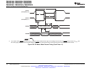
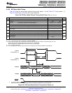
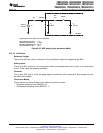
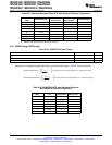
Typical Values of the Input Circuit Components:
Switch Resistance (R
on
): 1 kΩ
Sampling Capacitor (C
h
): 1.64 pF
Parasitic Capacitance (C
p
): 10 pF
Source Resistance (R
s
): 50 Ω
28x DSP
Source
Signal
TMS320F2809, TMS320F2808, TMS320F2806
TMS320F2802, TMS320F2801, TMS320C2802
TMS320C2801, TMS320F28016, TMS320F28015
www.ti.com
SPRS230L–OCTOBER 2003–REVISED DECEMBER 2009
Figure 6-25. ADC Analog Input Impedance Model
6.10.7.2 Definitions
Reference Voltage
The on-chip ADC has a built-in reference, which provides the reference voltages for the ADC.
Analog Inputs
The on-chip ADC consists of 16 analog inputs, which are sampled either one at a time or two channels at
a time. These inputs are software-selectable.
Converter
The on-chip ADC uses a 12-bit four-stage pipeline architecture, which achieves a high sample rate with
low power consumption.
Conversion Modes
The conversion can be performed in two different conversion modes:
• Sequential sampling mode (SMODE = 0)
• Simultaneous sampling mode (SMODE = 1)
Copyright © 2003–2009, Texas Instruments Incorporated Electrical Specifications 127
Submit Documentation Feedback
Product Folder Link(s): TMS320F2809 TMS320F2808 TMS320F2806 TMS320F2802 TMS320F2801 TMS320C2802
TMS320C2801 TMS320F28016 TMS320F28015