


t
w(RSL1)
t
h(boot-mode)
(B)
V
DDIO
, V
DD3VFL
V
DDA2
, V
DDAIO
(3.3 V)
XCLKIN
X1/X2
XRS
Boot-Mode
Pins
V
DD
, V
DD1A18,
V
DD2A18
(1.8 V)
XCLKOUT
I/O Pins
(C)
User-Code Dependent
User-Code Dependent
Boot-ROM Execution Starts
Peripheral/GPIO Function
Based on Boot Code
GPIO Pins as Input
OSCCLK/8
(A)
GPIO Pins as Input (State Depends on Internal PU/PD)
t
OSCST
User-Code Dependent
Address/Data/
Control
(Internal)
Address/Data Valid. Internal Boot-ROM Code Execution Phase
User-Code Execution Phase
t
d(EX)
TMS320F2809, TMS320F2808, TMS320F2806
TMS320F2802, TMS320F2801, TMS320C2802
TMS320C2801, TMS320F28016, TMS320F28015
www.ti.com
SPRS230L–OCTOBER 2003–REVISED DECEMBER 2009
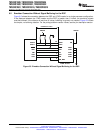
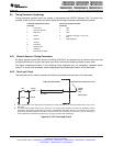
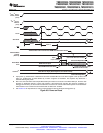
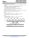
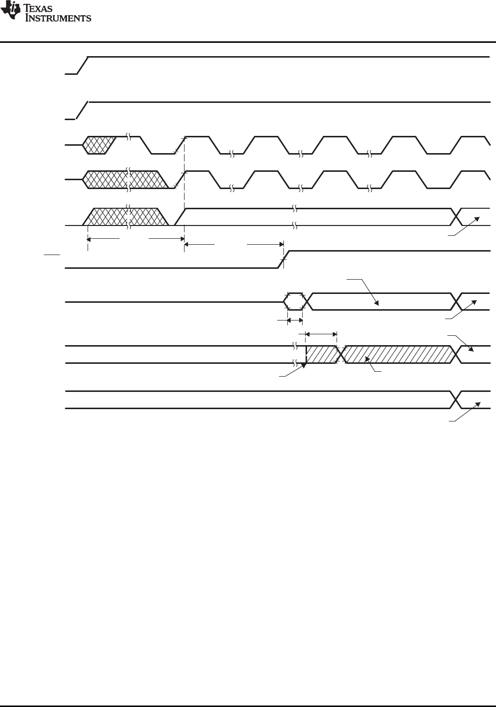
A. Upon power up, SYSCLKOUT is OSCCLK/2. Since the XCLKOUTDIV bits in the XCLK register come up with a reset
state of 0, SYSCLKOUT is further divided by 4 before it appears at XCLKOUT. This explains why XCLKOUT =
OSCCLK/8 during this phase.
B. After reset, the boot ROM code samples Boot Mode pins. Based on the status of the Boot Mode pin, the boot code
branches to destination memory or boot code function. If boot ROM code executes after power-on conditions (in
debugger environment), the boot code execution time is based on the current SYSCLKOUT speed. The SYSCLKOUT
will be based on user environment and could be with or without PLL enabled.
C. See Section 6.8 for requirements to ensure a high-impedance state for GPIO pins during power-up.
Figure 6-8. Power-on Reset
Copyright © 2003–2009, Texas Instruments Incorporated Electrical Specifications 107
Submit Documentation Feedback
Product Folder Link(s): TMS320F2809 TMS320F2808 TMS320F2806 TMS320F2802 TMS320F2801 TMS320C2802
TMS320C2801 TMS320F28016 TMS320F28015