


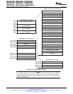

Digital Value + 0,
Digital Value + 4096
Input Analog Voltage * ADCLO
3
when input ≤ 0 V
when 0 V < input < 3 V
when input ≥ 3 VDigital Value + 4095,
TMS320F2809, TMS320F2808, TMS320F2806
TMS320F2802, TMS320F2801, TMS320C2802
TMS320C2801, TMS320F28016, TMS320F28015
www.ti.com
SPRS230L–OCTOBER 2003–REVISED DECEMBER 2009
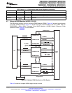
4.6 Enhanced Analog-to-Digital Converter (ADC) Module
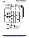
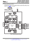
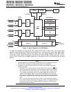
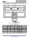
A simplified functional block diagram of the ADC module is shown in Figure 4-7. The ADC module
consists of a 12-bit ADC with a built-in sample-and-hold (S/H) circuit. Functions of the ADC module
include:
• 12-bit ADC core with built-in S/H
• Analog input: 0.0 V to 3.0 V (Voltages above 3.0 V produce full-scale conversion results.)
• Fast conversion rate: Up to 80 ns at 25-MHz ADC clock, 12.5 MSPS
• 16-channel, MUXed inputs
• Autosequencing capability provides up to 16 "autoconversions" in a single session. Each conversion
can be programmed to select any 1 of 16 input channels
• Sequencer can be operated as two independent 8-state sequencers or as one large 16-state
sequencer (i.e., two cascaded 8-state sequencers)
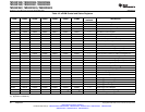
• Sixteen result registers (individually addressable) to store conversion values
– The digital value of the input analog voltage is derived by:
A. All fractional values are truncated.
• Multiple triggers as sources for the start-of-conversion (SOC) sequence
– S/W - software immediate start
– ePWM start of conversion
– XINT2 ADC start of conversion
• Flexible interrupt control allows interrupt request on every end-of-sequence (EOS) or every other EOS.
• Sequencer can operate in "start/stop" mode, allowing multiple "time-sequenced triggers" to
synchronize conversions.
• SOCA and SOCB triggers can operate independently in dual-sequencer mode.
• Sample-and-hold (S/H) acquisition time window has separate prescale control.
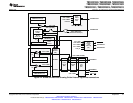
The ADC module in the 280x has been enhanced to provide flexible interface to ePWM peripherals. The
ADC interface is built around a fast, 12-bit ADC module with a fast conversion rate of up to 80 ns at
25-MHz ADC clock. The ADC module has 16 channels, configurable as two independent 8-channel
modules. The two independent 8-channel modules can be cascaded to form a 16-channel module.
Although there are multiple input channels and two sequencers, there is only one converter in the ADC
module. Figure 4-7 shows the block diagram of the ADC module.
The two 8-channel modules have the capability to autosequence a series of conversions, each module
has the choice of selecting any one of the respective eight channels available through an analog MUX. In
the cascaded mode, the autosequencer functions as a single 16-channel sequencer. On each sequencer,
once the conversion is complete, the selected channel value is stored in its respective RESULT register.
Autosequencing allows the system to convert the same channel multiple times, allowing the user to
perform oversampling algorithms. This gives increased resolution over traditional single-sampled
conversion results.
Copyright © 2003–2009, Texas Instruments Incorporated Peripherals 63
Submit Documentation Feedback
Product Folder Link(s): TMS320F2809 TMS320F2808 TMS320F2806 TMS320F2802 TMS320F2801 TMS320C2802
TMS320C2801 TMS320F28016 TMS320F28015