


TMS320F2809, TMS320F2808, TMS320F2806
TMS320F2802, TMS320F2801, TMS320C2802
TMS320C2801, TMS320F28016, TMS320F28015
www.ti.com
SPRS230L–OCTOBER 2003–REVISED DECEMBER 2009
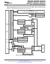
3.2.17 Peripheral Frames 0, 1, 2 (PFn)
The 280x segregate peripherals into three sections. The mapping of peripherals is as follows:
PF0: PIE: PIE Interrupt Enable and Control Registers Plus PIE Vector Table
Flash: Flash Control, Programming, Erase, Verify Registers
Timers: CPU-Timers 0, 1, 2 Registers
CSM: Code Security Module KEY Registers
ADC: ADC Result Registers (dual-mapped)
PF1: eCAN: eCAN Mailbox and Control Registers
GPIO: GPIO MUX Configuration and Control Registers
ePWM: Enhanced Pulse Width Modulator Module and Registers
eCAP: Enhanced Capture Module and Registers
eQEP: Enhanced Quadrature Encoder Pulse Module and Registers
PF2: SYS: System Control Registers
SCI: Serial Communications Interface (SCI) Control and RX/TX Registers
SPI: Serial Port Interface (SPI) Control and RX/TX Registers
ADC: ADC Status, Control, and Result Register
I2C: Inter-Integrated Circuit Module and Registers
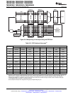
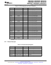
3.2.18 General-Purpose Input/Output (GPIO) Multiplexer
Most of the peripheral signals are multiplexed with general-purpose input/output (GPIO) signals. This
enables the user to use a pin as GPIO if the peripheral signal or function is not used. On reset, GPIO pins
are configured as inputs. The user can individually program each pin for GPIO mode or peripheral signal
mode. For specific inputs, the user can also select the number of input qualification cycles. This is to filter
unwanted noise glitches. The GPIO signals can also be used to bring the device out of specific low-power
modes.
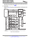
3.2.19 32-Bit CPU-Timers (0, 1, 2)
CPU-Timers 0, 1, and 2 are identical 32-bit timers with presettable periods and with 16-bit clock
prescaling. The timers have a 32-bit count down register, which generates an interrupt when the counter
reaches zero. The counter is decremented at the CPU clock speed divided by the prescale value setting.
When the counter reaches zero, it is automatically reloaded with a 32-bit period value. CPU-Timer 2 is
reserved for the DSP/BIOS Real-Time OS, and is connected to INT14 of the CPU. If DSP/BIOS is not
being used, CPU-Timer 2 is available for general use. CPU-Timer 1 is for general use and can be
connected to INT13 of the CPU. CPU-Timer 0 is also for general use and is connected to the PIE block.
3.2.20 Control Peripherals
The 280x devices support the following peripherals which are used for embedded control and
communication:
ePWM: The enhanced PWM peripheral supports independent/complementary PWM
generation, adjustable dead-band generation for leading/trailing edges,
latched/cycle-by-cycle trip mechanism. Some of the PWM pins support HRPWM
features.
eCAP: The enhanced capture peripheral uses a 32-bit time base and registers up to four
programmable events in continuous/one-shot capture modes.
This peripheral can also be configured to generate an auxiliary PWM signal.
Copyright © 2003–2009, Texas Instruments Incorporated Functional Overview 39
Submit Documentation Feedback
Product Folder Link(s): TMS320F2809 TMS320F2808 TMS320F2806 TMS320F2802 TMS320F2801 TMS320C2802
TMS320C2801 TMS320F28016 TMS320F28015