


TMS320F2809, TMS320F2808, TMS320F2806
TMS320F2802, TMS320F2801, TMS320C2802
TMS320C2801, TMS320F28016, TMS320F28015
SPRS230L–OCTOBER 2003–REVISED DECEMBER 2009
www.ti.com
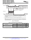
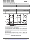
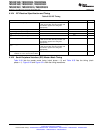
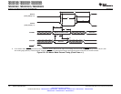
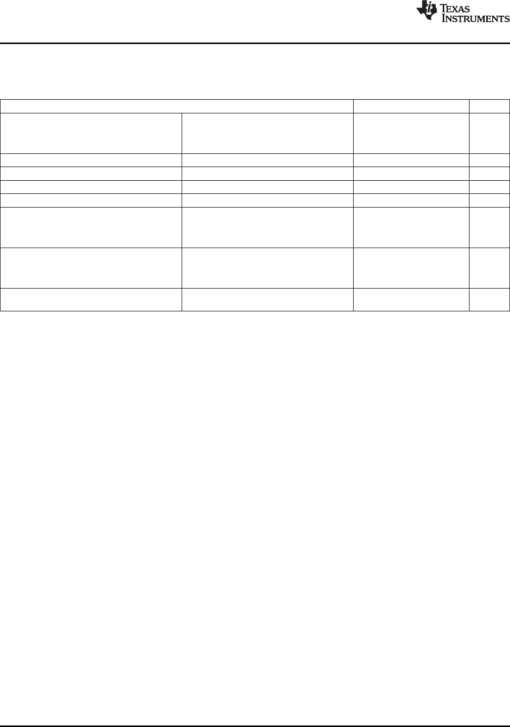
6.10.4 I2C Electrical Specification and Timing
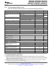
Table 6-33. I2C Timing
TEST CONDITIONS MIN MAX UNIT
f
SCL
SCL clock frequency I2C clock module frequency is between 400 kHz
7 MHz and 12 MHz and I2C prescaler and
clock divider registers are configured
appropriately
V
il
Low level input voltage 0.3 V
DDIO
V
V
ih
High level input voltage 0.7 V
DDIO
V
V
hys
Input hysteresis 0.05 V
DDIO
V
V
ol
Low level output voltage 3 mA sink current 0 0.4 V
t
LOW
Low period of SCL clock I2C clock module frequency is between 1.3 μs
7 MHz and 12 MHz and I2C prescaler and
clock divider registers are configured
appropriately
t
HIGH
High period of SCL clock I2C clock module frequency is between 0.6 μs
7 MHz and 12 MHz and I2C prescaler and
clock divider registers are configured
appropriately
l
I
Input current with an input voltage –10 10 μA
between 0.1 V
DDIO
and 0.9 V
DDIO
MAX
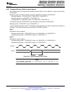
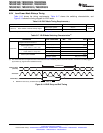
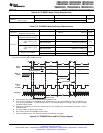
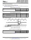
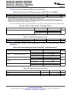
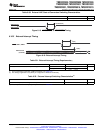
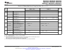
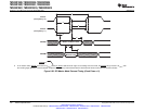
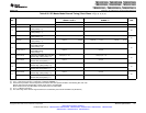
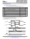
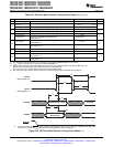
6.10.5 Serial Peripheral Interface (SPI) Master Mode Timing
Table 6-34 lists the master mode timing (clock phase = 0) and Table 6-35 lists the timing (clock
phase = 1). Figure 6-20 and Figure 6-21 show the timing waveforms.
118 Electrical Specifications Copyright © 2003–2009, Texas Instruments Incorporated
Submit Documentation Feedback
Product Folder Link(s): TMS320F2809 TMS320F2808 TMS320F2806 TMS320F2802 TMS320F2801 TMS320C2802
TMS320C2801 TMS320F28016 TMS320F28015