


Studio Color LCD Controller
Powering On the Controller
2-27
2
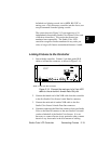
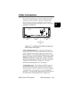
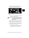
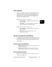
3. Insert the controller power key into the controller’s front
panel power key switch and turn the key clockwise. The
location of the key switch is shown in Figure 2-18.
Figure 2-18. Locations of the power key switch, the
<Standby> key and Standby LED.
Caution Do not touch the joystick when applying
power to the controller; the controller
uses the initial position of the joystick as a
reference point.
4. The LCD window briefly shows the Boot version number and
all LEDs flash. In a moment the Standby, Address, and any
initialized or programmed Address/Preset LEDs light.
5. If a RAM card containing memory (memories, pages, presets,
etc.) is inserted in the slot, the contents of the RAM card are
checked against the contents of memory.
• If the contents of memory and the RAM card match, the
controller is placed in mirror mode and all future
programming is automatically copied to the card.
Standby key
and LED
Power key switch
ADVANCE
LIGHTWAVE
audio
level
erase
recordselect
home
page
cursor
construct
PAGEMEMORYINTENSITY
MEMORY CARD
POWER
STANDBY
rate
USER
auto
PRE SET
ADDRESS
1
3
5
7
2
4
6
8
12
3
4
56
7
8
slave
Studio Color