


Studio Color LCD Controller
Pinouts and Wiring Diagrams
C-3
C
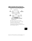
IBM-Compatible Wiring Diagrams
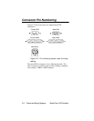
Figure C-3 shows wiring diagrams for IBM-compatible
systems:
Figure C-3. Wiring cables for backing up or
restoring controller memory using an IBM-
compatible machine.
Note Male connectors are shown for simplicity.
The top diagram could be used to wire either a straight-
through cable or a DB9-to-DB25 adapter.
The null modem wiring diagram could be used only to
crossload between two controllers as described in the section
titled “Crossloading” on page 7-30.
DB9 DB25
Pin # Pin #
2 (Rcv)
3 (Tr)
4 (DTR)
5 (Grnd)
2 (Tr)
3 (Rcv)
7 (Grnd)
20 (DTR)
Straight-Through
Null Modem
Pin # Pin #
2 (Rcv)
3 (Tr)
4 (DTR)
5
(
Grnd
)
2 (Rcv)
3 (Tr)
4 (DTR)
5
(
Grnd
)
DB9
DB9