


2-16
Connecting Fixtures
Studio Color LCD Controller
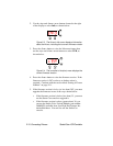
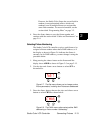
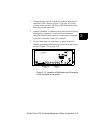
Terminators
The last device on each link must have a 120 ohm, 1/4 watt
(minimum) terminator attached to its Data Out connector.
You can construct terminators by following the instructions
in Figure 2-11:
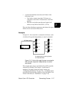
Figure 2-11. Constructing a data cable terminator.
Connection Rules
Before continuing, you need to understand the following
rules:
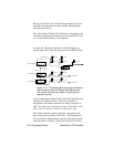
• Each controller supports up to 8 unique fixtures. If you
want to connect more than 8 fixtures to a controller, some
of the fixtures will have to share the same fixture
number, and will thus respond to the same set of control
commands.
Note The Studio Color fixture has several built-in random
(or unsynchronized) effects which work randomly
even if multiple fixtures are assigned the same fixture
number. For more information, see the section titled
“Programming Hints” on page 3-2.
• You can expand your system beyond 8 independently-
operating fixtures by connecting master and slave
controllers together.
120
Ω
1. Obtain a male XLR connector.
2. Disassemble the connector.
3. Solder a 120 ohm resistor, minimum
of 1/4 watt, between pins 2 and 3.
4. Reassemble the connector.
5. Install the terminator in the Data Out
port of the last device in the link.