


Studio Color LCD Controller
Connecting Fixtures
2-15
2
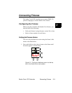
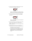
Constructing Cabling
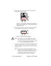
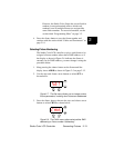
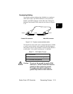
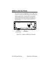
You should construct cables using shielded, two-conductor
cable with a male 3-pin XLR connector at one end and a
female 3-pin XLR connector on the other end. Pinouts for
both male and female XLR connectors are shown in Figure
2-10.
Figure 2-10. Properly-constructed data cable.
You should test each cable with a voltage/ohm meter (VOM)
to verify correct polarity and to make sure that the negative
and positive pins are not grounded or shorted to the shield or
to each other. Also, make sure that pin 1 is shielded.
Caution Do not use the ground lug on the XLR
connectors. Do not connect the shield to
ground or allow contact to ground.
Grounding the shield could cause a
ground loop and/or erratic behavior.
Table 2-1. XLR Cable Pinouts
Pin 1 is the shield
Pin 2 is the data complement (negative)
Pin 3 is the data true (positive)
Negative
Male XLR connector
Positive
ShieldNegative
Female XLR connector