


Studio Color LCD Controller
Pinouts and Wiring Diagrams
C-1
C
Appendix C
Pinouts and Wiring
Diagrams
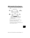
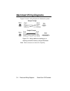
This Appendix lists connector pinouts and shows how to wire
various types of cabling you can use to back up and restore
controller memory to a personal computer, or to crossload
memory between controllers.
This Appendix should be used by highly-technical
individuals who are already familiar with how to wire
cabling. Other users should consult the instructions in
Chapter 7.
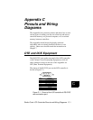
DTE and DCE Equipment
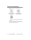
The RS-232CC port on the rear panel of the LCD controller
is DCE (Data Circuit-Terminating Equipment), while all
other connectors shown in the rest of this Appendix are
DTE (Data Terminal Equipment).
The pinout of the RS-232C port on the LCD controller is
shown in Figure C-1:
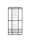
Figure C-1. Pinout of the LCD controller’s RS-232C
communication port.
12345
6789
Pin #
1
2
3
4
5
6
7
8
9
Definition
not used
TxD (transmit data)
RxD (receive data)
Data Terminal Ready (+5V)
GND (signal ground)
not used
not used
not used
not used