


Studio Color LCD Controller
Binary Access Table
A-1
A
Appendix A
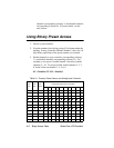
Binary Access Table
The binary values listed in Table A-1 equate to the first 10
channels of analog input channels 1 to 12, with the least
significant binary bit being channel 1. You can use Table A-1
as shown below:
• Determining which analog controller channels to enable
and disable when you are using binary preset access. See
“Using Binary Preset Access” on page A-2.
• Determining which Studio Color LCD controller Preset
LED will be ON for a preset selected using binary preset
access.
Explanation of the Table
Table A-1 has a total of 13 columns with the meanings
explained below:
• Preset No.: Lists preset numbers sequentially from 1 to
1023.
• Preset Key: Shows which Preset LED will be ON for
the selected preset in binary preset access. For example,
if you use preset 600 in binary preset access, the preset
<8>
LED will be ON.
• Preset Level: Each group of eight presets counts as one
level. For example, preset numbers 1—8 are in preset
level 1; preset numbers 9—16 are in preset level 2, etc.
The first 12 preset levels (presets 1—96) are used in 12-
level preset access mode and the remaining preset levels
are listed for your information.
• Analog Controller Channel Number: A group of 10
columns that give the binary equivalent of the preset
number. To use that number, enable analog controller