


Studio Color LCD Controller
Connecting Fixtures
2-19
2
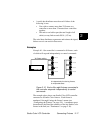
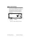
be linked to a lighting console via its MIDI, RS-232C or
analog ports. Only the master controller (not the slaves) can
accept commands from the lighting console.
The system shown in Figure 2-13 can support up to 24
independently-functioning Studio Color fixtures (8 for each
of the three controllers). Also notice that fixtures are
numbered non-sequentially. The Studio Color LCD
controller recognizes fixtures numbered in any order you
wish, as long as all fixtures are numbered between 1 and 8.
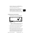
Linking Fixtures to the Controller
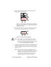
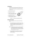
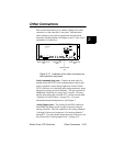
1. Start with the controller. Connect 3-pin data-grade XLR
cable to its Data Out connector, as shown in Figure 2-14:
Figure 2-14. Connect the male end of a 3-pin XLR
cable to the controller’s female Data Out port.
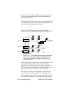
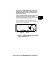
2. Connect the female end of the XLR cable from the controller
to the first Studio Color fixture’s male Data In connector.
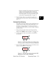
3. Connect the male end of another XLR cable to the first
Studio Color fixture’s female Data Out connector.
4. Continue connecting the Data Out connector from one Studio
Color to the Data In connector to the next Studio Color until
you have linked all of the Studio Color fixtures. It is not
necessary to connect fixtures in any particular order; connect
them in a way that results in the least amount of cabling.
DATA LINK
OUT
CAUTION
WARNING
PERSONALITY
SLAVE
MASTER
RS-232
SERIAL PORT
1-6
ANALOG INPUTS
7-12
REMOTE
ENABLE
FUSE
CAUTION
voltage
select
1 2 3 4
AB
MIDI
IN OUT
STEREO
AUDIO
INPUT
115
To reduce the risk of fire or
electric shock, do not expose
this device to rain or moisture.
L
R
IMPORTANT SAFETY INFORMATION. SEE INSTRUCTION MANUAL BEFORE USE.
WICHTIGE SICHERHEITSI NFORMATIONEN. BEDIENUNG SANLEITUN G VOR GEBRA UCH LESEN!
D'IMPORT ANTE CONSIG NE DE S
É
CURIT
É
. VOYE Z LE MANUEL D 'INSTRU CTION AVANT L 'UTILISATION DE L'APPAREIL .
This device complies with part 15 of the FCC rules.
Operation is su bject to the fo llowing tw o conditions:
(1) This devi ce may not cause harmful i nterferences,
and (2) this dev ice must accept any i nterference
that may cause unde sired operatio n.
To prevent electric shock, do
not remove cover. No user
serviceable parts inside.Refer
servicing to qualified service
personnel. Replace fuse with
same type and rating.
RATING INFOR MATION
VOLTAGE: 1 15VAC/230VAC
CURRENT: 0.25A/0.15A
FREQUENC Y: 5 0-60 HZ
115 V 0.5 A, SLOW BLOW
230 V 0.315 A, SLOW BLOW
1 2 3 4
1 2 3 4 5 6 7 8
1 2 3 4 5 6 7 8
Attach a male 3-pin XLR connector
MODEL
SERIAL
DATE QC
VOLTAG E
HZ
230
15FM123456
Cyberlight LCD Controller
50
80590001
ETL Listed
Conforms to
UL Std. 1950
Cer tified to
CAN/CSA C22.2 No. 950
67501
R
C
R
LIGHTWAVE RESEARCH
2217 West Braker Lane
Austin, Texas U.S.A.