Basic Operation
Lexicon
2-10
3. Component Video Output Connectors (continued)
The component video output connectors provide progressive-
scan and interlaced component video output. Progressive-scan
component video output converts interlaced video signals to
progressive video signals, doubling the amount of video
information sent to a compatible display device. The result is a
higher quality, more stable image with fewer video artifacts.
4. Composite Video Output Connectors
Provide composite video output. All versions include two RCA
connectors labeled VIDEO. All composite video output
connectors can be used at the same time.
5. S-video Output Connector
Provide S-video output. All versions include one S-video
connector labeled S-VIDEO.
6. Euro or Peritel (TV A/V) Connector
Provides composite, S-video, or RGB video and two channels of
audio output. Some versions include one SCART connector
labeled TV A/V CONNECTOR. The Video Out parameter (3-27)
controls video output format when the RT-10 is using the Euro
or Peritel (TV A/V) connector.
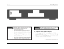
Rear Panel Overview (continued from page 2-9)
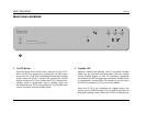
The numbers in the RT-10 rear panel illustration shown on page
2-9 correspond to the numbered items that continue below.
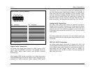
7. Digital Audio Output Connectors
Provide digital audio output. All versions include one coaxial
and one optical connector labeled S/PDIF, as well as one XLR
connector labeled AES/EBU. The connector labeled AES/EBU
provides S/PDIF digital audio output with AES/EBU electrical
characteristics.
8. Analog Audio Output Connectors
Provide analog audio output. All models include eight RCA
connectors labeled Front L/R (2 pairs), Surround L/R, Center,
and Sub. The Audio Out parameter (3-16) can be used to
configure these connectors to provide 2- or 5.1-channel analog
audio output.
9. Trigger Input Switch
Enables and disables trigger control when the trigger input
connector (number 10) on the RT-10 is connected to the
trigger output connector on an associated component.
When the trigger input connector on the RT-10 is connected to
the trigger output connector on an associated component and
the trigger input switch is set to ON, the RT-10 responds when
standby mode is activated or deactivated for the connected
component. Whenever the trigger input switch is set to ON,
the remote control POWER button cannot be used to
activate and deactivate standby mode, even when the RT-10
is not using the trigger input connector.


