


62 Chapter 4 Selecting the media bay modules for your system
P0609324 01
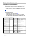
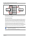
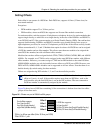
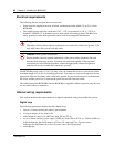
Figure 25 DS30 bus model
DS30 bus numbers are set using the number 4, 5, and 6 DIP switches on the back or underside of
the media bay modules. The exception is the FEM module. The FEM DIP switches turn on ports,
each of which consumes one DS30 bus.
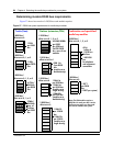
Explaining Double Density
BCM 3.0 software introduced the concept of single and double density for DS30 buses supporting
station modules. On these buses the B2 bus blocks are reconfigured as B1 bus blocks, thereby,
doubling telephone capacity. However, only DSM16+, DSM32+ and ASM/ASM8+ modules can
support the second set of DNs. The DSM16+ and DSM32+ modules can be configured for either
single density, which access only the top 16 DNs, or double density, which accesses all 32 DNs.
Default BCM 3.0 and newer systems are configured as Partial Double Density (PDD) systems, in
that they maintain DS30 06 and 07 in the original configuration of 16 DNs per bus. This
accommodates those systems which use Companion. The system can be set to Full Double Density
(FDD) at system startup or once the system is setup. When the system is set to FDD, DS30 06 and
07 allow access to the second set of DNs, and they are no longer available for Companion
operation.
Note: Devices that share a DS30 bus must be identical. Use two DSM 16+ modules set
to double density on a single DS30 bus.
A DSM 32+ set to double density requires a full DS30 bus.
DS256
on MSC
DS30 bus 02
DS30 bus 03
DS30 bus 04
DS30 bus 05
DS30 bus 06
DS30 bus 07
DS30 blocks
available to modules
in a 2/6 split
Four offsets per bus
DS30 blocks
available to modules
in a 3/5 split