


Chapter 4 Selecting the media bay modules for your system 61
Installation and Maintenance Guide
Upgrading from an existing Norstar system
A special media bay module allows you to convert existing Norstar expansion modules from the
Norstar ICS to full Business Communications Manager capability.
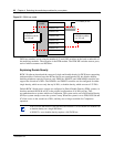
The FEM allows you to connect a maximum of six Norstar expansion modules to a BCM1000.
Each expansion module connection requires one DS30 bus, therefore, the BCM1000 used for this
purpose can only support one FEM module (and no BCM1000e) if you are converting a
fully-configured Norstar system.
Determining system capacity
After you have selected the modules you require, you must ensure that the Business
Communications Manager can support all the modules. This is determined by the DS30 bus
requirements of each module.
The following sections describe these bus blocks and how you fit your modules into the overall
system planning.
Understanding DS30 bus blocks
A DS30 bus is a block of virtual pathways on the media services card (MSC).
On a default system, six DS30 bus blocks can be assigned to media bay modules. The block to
which the module is assigned determines the range of line (trunk) numbers or extension numbers
(DNs) that can be allocated by the module to the equipment connected to that module. The first
and last DS30 blocks are permanently routed to the PEC DSPs to support internal Business
Communications Manager functions such as voice mail, VoIP trunks, and IP telephony functions.
This configuration is called a 2/6 DS30 split.
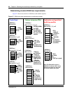
Changing the DS30 split
You can change the DS30 bus allocation to a 3/5 split to accommodate increased IP telephony or
VoIP trunk requirements. You do this by assigning DS30 07 to the voice data sector. This choice
should be made at system startup, but a default system can be changed through the Unified
Manager to a 3/5 split after startup if IP requirements increase. At startup, you indicate the split
you want when you run the Quick Start Wizard. Refer to the Programming Operations Guide for
details.
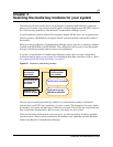
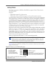
Figure 25 shows a model of how the DS30 bus blocks are a subgroup of the DS256 bus on the
MSC. The diagram also shows offsets, which are a subgroup of the DS30 blocks.
Warning: If you change the DS30 split from 3/5 to 2/6 after your system is configured,
you will lose all the data and optional application connections.