


34 Chapter 2 Telephony hardware
P0609324 01
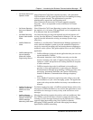
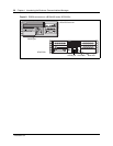
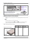
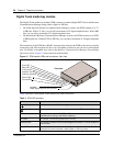
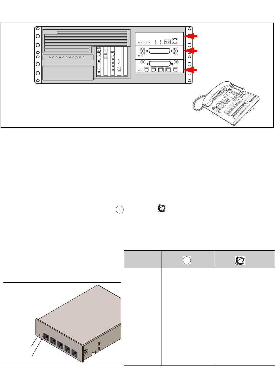
Figure 11 Telephony hardware components.
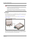
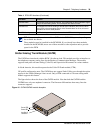
Media bay module common features
Media bay modules are designed within a common casing, which includes the following common
features:
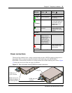
LEDs
All media bay modules have power and status LEDS.
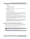
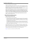
Figure 12 shows the location of the (Power) and (Status) on a CTM. These LEDs are
located in the same place on all modules. Table 2 describes the common LED states.
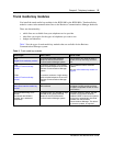
Table 2 Module Power and Status LED states
LED state
Power
Status
Figure 12 Module LED locations
Indicates state of
module power
Indicates condition of
module status
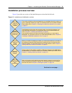
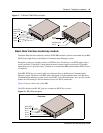
“Trunk media bay modules”
on page 37
“Station media bay modules”
on page 42
“Specialized media bay
modules” on page 46
“Telephones and adapters”
on page 48
Refer to “Media bay module availability by region” on
page 237 and “Trunk availability by region” on page
239 to determine which media bay modules and which
types of trunk lines are available in your location.
CTM
Power LED
Status LED