


152 Chapter 12 Installing Analog Terminal Adapters
P0609324 01
Connecting the ATA 2
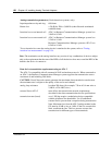
After the correct environment has been set up, connect the Business Communications Manager
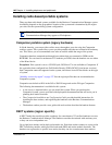
and the analog device to the ATA 2, then connect the module power. Refer to Figure 61.
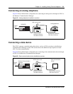
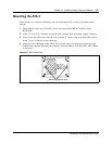
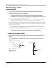
Figure 61 ATA 2 top view
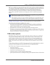
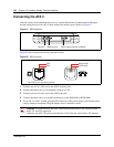
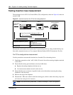
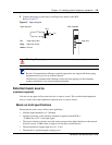
Figure 62 shows the pinouts for the connection cables.
Figure 62 ATA 2 pin outs
1 Connect one end of a line cord to the ATA2 Terminal jack.
2 Connect the other end to your telephone, modem or FAX.
3 Connect one end of a line cord to the ATA2 Line jack.
4 Connect the other end to an available station port on the BCM1000 or BCM1000e.
5 For a 120 V or 230 V system, plug the DIN connector of the power supply cord into the power
supply connector receptacle. Plug the adapter into a standard ac outlet.
Caution: In North America, the ATA 2 must be powered from a Class 2 power source
that is UL and CSA approved.
In Europe, the ATA 2 must be powered from a Class II power source that is CE marked.
=
24 V ~
0.006 A
Telephone jackLine jack Power supply connector receptacle
TCM*
TCM*
Ring (B-Lead)
Tip (A-Lead)
Line Jack Terminal Jack
* The TCM input is not polarity sensitive.