


212 Chapter 18 Replacing a power supply
P0609324 01
6 If you have not already done so, install a redundant fan into the unit. Refer to “Adding or
replacing a cooling fan” on page 197.
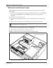
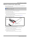
7 Inside the cabinet, reconnect the power supply and fan cables.
8 Reconnect the power supply and fan cables.
9 Replace the cover.
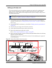
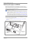
10 Ensure that you position the power modules correctly before inserting them into the power
supply housing.
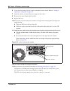
a The green LED sits at the top of the unit.
b Check the rocker switch on the left side of the module and ensure that it is in the OFF
position.
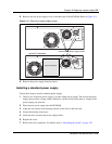
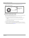
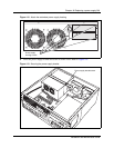
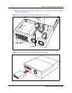
11 Insert the power modules into the redundant power supply housing at the back of the server.
a The face of the module is flush with the casing. You hear a click when it is properly
seated.
b Secure each module with a screw through the tab on the right side of the module.
These holes align with the middle two holes on the right of the power supply housing.
Refer to Figure 120.
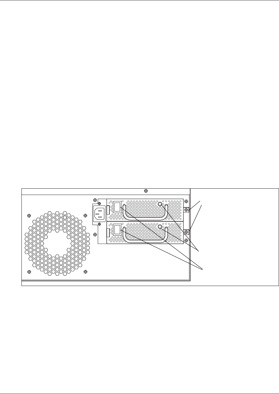
Figure 120 Insert and attach the modules
12 Turn on the switches for both power modules.
13 Restore the units to operation as described in “Restarting the system” on page 170.
The Business Communications Manager system starts up when you connect the ac power
cord. System recovery takes several minutes to complete.
The LEDs on the power supply are on when the ac power is connected.
Module screws.
Rocker switches
Power module status LED