


Chapter 2 Telephony hardware 35
Installation and Maintenance Guide
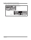
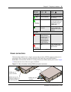
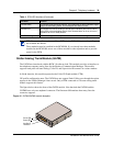
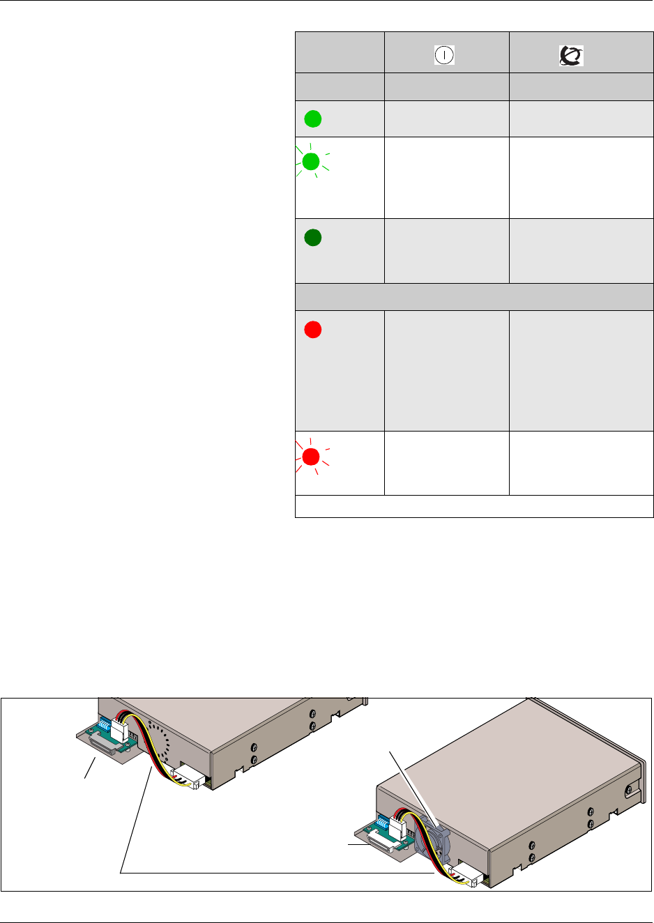
Power connections
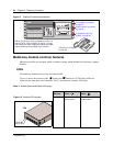
The back of the modules have a single connector that provides a DS256 connector and power to
the module. These connectors plug into the back of the media bay on the BCM1000 or
BCM1000e. Some modules also have a cooling fan that runs off the module power source. Figure
13 shows the rear views of the two types of modules.
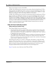
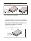
Figure 13 Rear of modules showing DS256 and power connectors
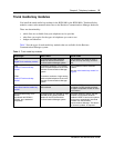
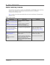
Green LED
On Normal operation All monitored services
are working.
Flashing
N/A KSU startup (slow flash)
or (fast flash) there may
be a problem with the
DS256 cable or the
DS256 clock
Off Module is not
powered
Module not powered
(reseat module) OR
hardware fault (replace
module)
*Red LED
On Power converter
failure. Power to
telephones may not
be within spec.
(check base unit
LEDs for possible
power issue or
replace module)
N/A
Flashing
N/A Loss of DS256 clock, or
DS256 cable may be
disconnected.
* Not all modules have red LEDs
LED state
Power
Status
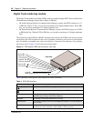
DS256 and power
connector
DS256 and
power connector
Cooling fan
Module wires are vul-
nerable to breakage.
See Warning below.