


88 Chapter 7 Setting media bay module DIP switches
P0609324 01
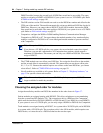
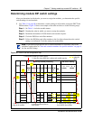
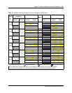
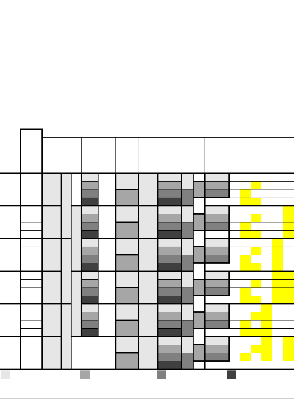
Table 11 shows possible DS30 bus numbers and offset configurations for each type of module, and
the corresponding switch settings for modules that only allow single density, or which are set to
single density, as may be the case for a DSM16+ or DSM32+.
The ASM/ASM8 settings are the same for either single or double density, except that you can only
use offset 0 and 1 on a DS30 bus that is not set for double density, such as for DS30 06 and 07 on a
PDD system.
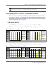
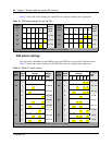
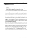
For DECT and FEM settings, refer to “DECT switch settings” on page 105 and “FEM switch
settings” on page 106.
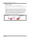
Example: Position your DSM 16 module (step 1), which requires one full DS30 bus (step 2), in
DS30 02 (step 3). Moving across, note that the offset is 0 (step 4). Set the DIP switches on the
module to match the DIP switch settings indicated for that offset (step 5).
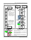
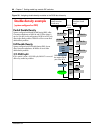
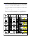
Table 11 Possible media bay module DIP switch settings, single density
DS30
bus
#
Offsets
Media bay module positioning
DIP switch settings
DSM
16/
16+
Offsets
0
DSM
32/
32+
Offsets
0
4x16
Offsets
0,1, 2, 3
Line
Exten.
ASM 8/
ASM8+
Offsets
0, 1, 2
DTM
Offsets
0
CTM/
GATM4
Offsets
0, 1, 2, 3
CTM 8/
GATM8
Offsets
0, 1, 2
BRI
Offsets
0, 1, 2, 3
12 3
(offset)
45 6
(DS30)
2
0
0 0 0Picks
up
ch.
#3
0 0 0 0 0 on on on on on on
1
1 1 1 1 on on off on on on
2
2 1 2 2 2 on off on on on on
3
3 3 on off off on on on
3
0
0 0 0Picks
up
ch.
#4
0 0 0 0 0 on on on on on off
1
1 1 1 1 on on off on on off
2
2 1 2 2 2 on off on on on off
3
3 3 on off off on on off
4
0
0 0 0Picks
up
ch.
#5
0 0 0 0 0 on on on on off on
1
1 1 1 1 on on off on off on
2
2 1 2 2 2 on off on on off on
3
3 3 on off off on off on
5
0
0 0 0Picks
up
ch.
#6
0 0 0 0 0 on on on on off off
1
1 1 1 1 on on off on off off
2
2 1 2 2 2 on off on on off off
3
3 3 on off off on off off
6
0
0 0 0Picks
up
ch.
#7
0 0 0 0 0 on on on off on on
1
1 1 1 1 on on off off on on
2
2 1 2 2 2 on off on off on on
3
3 3 on off off off on on
7***
0
0
Not
supported
0 0 0 0 0 on on on off on off
1
1 1 1 on on off off on off
2
1 2 2 2 on off on off on off
3
3 on off off off on off
Module set to offset 0 Module set to offset 1 Module set to offset 2 Module set to offset 3
Each shaded square represents the amount of the DS30 bus, and the offset, which the module requires.
***If your system is configured with a 3/5 DS30 split, DS30 07 is not available to media bay modules.