


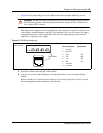

138 Chapter 10 Wiring the modules
P0609324 01
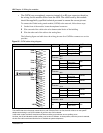
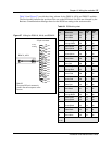
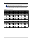
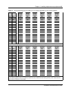
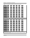
Table 35 and Figure 58 provide the wiring scheme for the eight pairs that connect to an ASM.
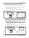
3 Plug the female amphenol connector into the interface on the front of the module.
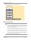
4 Set up any mobile system you are using.
• Ensure the base stations are correctly installed and connected to the appropriate modules
on the Business Communications Manager hardware. In the case of the NetVision wireless
system, ensure that the access point is correctly set up to connect to the BCM1000 LAN or
WAN.
• Configure and register the handsets according to the instructions provided for each type of
system.
— Companion: Programming Operations Guide
—DECT: DECT Installation and Maintenance Guide
— T7406: T7406 Cordless Handset Installation Guide
Table 35 ASM wiring chart
Pin Wire color Port Set
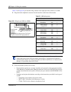
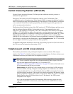
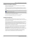
Figure 58 Wiring for an ASM 8 or ASM8+
26 White-Blue X01 1
1 Blue-White X01 1
27 White-Orange X02 2
2 Orange-White X02 2
28 White-Green X03 3
3 Green-White X03 3
29 White-Brown X04 4
4Brown-White X044
30 White-Slate X05 5
5 Slate-White X05 5
31 Red-Blue X06 6
6 Blue-Red X06 6
32 Red-Orange X07 7
7 Orange-Red X07 7
33 Red-Green X08 8
8 Green-Red X08 8
34-50 no connection
9-25
Note: Refer to “Line and extension numbers for specific modules” on page 91 to see the
relationship between the DS30 bus number and the DNs. Configuration information is
included in the chapters on setting up modules and DNs in the Business Communications
Manager Programming Operations Guide.
8T
33R
32R
7T
31R
6T
30R
5T
29R
4T
28R
3T
27R
2T
26R
1T
25-pair female
amphenol
connector
WARNING: Ensure that you have Tip (T) and
Ring (R) connected to the appropriate pins.