


36 Chapter 2 Telephony hardware
P0609324 01
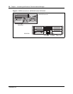
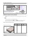
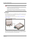
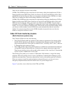
DIP switches
The six DIP switches that you use to set the DS30 bus blocks and offsets are found either on the
bottom of the module or on the rear, behind the power connector. Figure 14 shows the possible
locations of the DIP switches on the modules.
For more information about setting DIP switches, refer to Chapter 8, “Installing media bay
modules,” on page 107.
Figure 14 DIP switch positions on the modules
The Global Analog Trunk Module (GATM), introduced in BCM 3.5, and the (Global) Analog
Station Module (ASM8+), introduced with BCM 3.6, have a second set of DIP switches that can
be set to a specific country setting to set to allow automatic firmware upgrades to the module,
based on the country profile chosen for the system during startup.
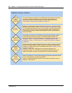
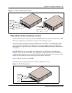
Warning: Media bay module wire shorts
The wires that connect the media bay module daughter board to the module can become
pinched between the module and the BCM1000 media bay if you insert the modules off
the straight or with too much force. This will cause a short in the equipment and could stop
the Business Communications Manager from restarting.
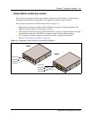
Note: Some of the new modules, such as the DECT module, do not have this wiring
configuration. However, inserting the module carefully and correctly is still important to
securely connect the power connector on the module to the backplane of the media bay.
Rear of module
DIP switches
Underside of module
Top of module