


Chapter 7 Setting media bay module DIP switches 91
Installation and Maintenance Guide
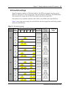
Line and extension numbers for specific modules
The switch settings on the media bay module determine the line numbers and extension numbers
the modules use. The tables in this section show the correspondence between DS30 bus numbers,
switch settings, and the line/extension numbers for each type of module. The DS30 bus and switch
settings correspond with Table 11 on page 88.
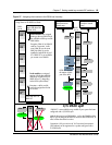
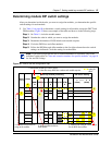
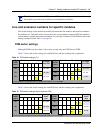
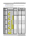
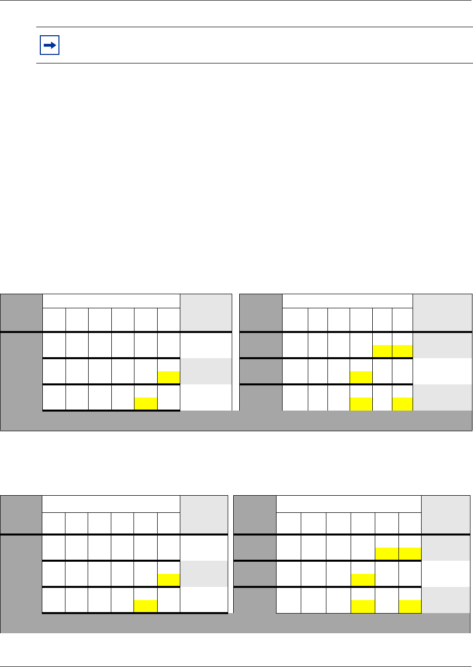
DTM switch settings
Although DTMs have more than 16 lines, they occupy only one DS30 bus per DTM.
Table 13 shows the switch settings for each DS30 bus, and the resulting line assignments.
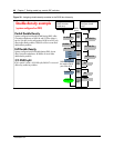
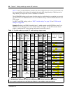
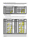
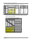
Table 14 shows the switch settings for each DS30 bus, and the resulting line assignments.
Tip: Create a label with the DS30 bus and DIP switch settings, and stick it to the front of
the module to provide ease of reference for maintenance activities.
Table 13 DTM switch settings (T1)
Select
DS30
bus #
Enter these switch settings
To assign
these lines
Select
DS30
bus #
Enter these switch settings
To assign
these lines
123456 123456
02
on on on on on on
211-234
05
on on on on
121-144
off off
03
on on on on on
181-204
06
on on on on on
91-114
off off
04
on on on on on
151-174
07
1
on on on on
61-84
off off off
1
If your system is configured with a 3/5 DS30 split, DS30 07 is not available.
Table 14 DTM switch settings (North American PRI)
Select
DS30
bus #
Enter these switch settings
To assign
these
lines
Select
DS30
bus #
Enter these switch settings
To assign
these
lines
123456 12 3 456
02
on on on on on on
211-233 05
on on on on
121-143
off off
03
on on on on on
181-203 06
on on on on on
91-113
off off
04
on on on on on
151-173 07
1
on on on on
61-83
off off off
1
If your system is configured with a 3/5 DS30 split, DS30 07 is not available.