


142 Chapter 11 Installing telephones and peripherals
P0609324 01
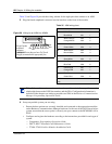
Central Answering Position (CAP/eCAP)
Create a Central Answering Position (CAP) that provides additional auto dial positions or
additional line appearances.
The legacy CAP consists of an M7324 telephone with one or two CAP modules. This
configuration requires a Supplementary Power Supply (SAPS) to support the additional modules.
Each CAP module provides 48 programmable keys with indicators. If the telephone is configured
as an extended CAP (eCAP) in system programming, the module supports line appearances as
well as any memory key functions.
The Business Series Terminal version of the CAP consists of a T7316E telephone and from one to
nine Key Indicator Modules (KIMs). Each module provides 24 programmable keys with
indicators. If the telephone is configured as an eCAP, a maximum of four modules can be added
(eKIMs). A T7316E+eKIM can support line appearances, multiple appearances of a target line,
and Hunt group designators in additional to memory key programming on the eKIMs. A T7316E/
KIM configuration that is not configured as an eCAP can support up to nine ordinary KIMs
(OKIMs). In this configuration, only memory button programming is supported. A Supplementary
Power Supply is required after the fifth module is added. Programming note: The T7316E+eKIM
does not support auto dial keys programmed with Hunt group DNs.
For detailed configuration information, refer to the Programming Operations Guide. Also refer to
the CAP user card for instructions about using a CAP.
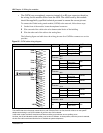
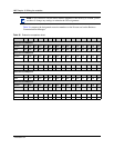
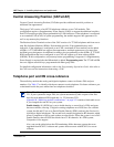
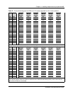
Telephone port and DN cross-reference
The media bay module that analog and digital telephones connect to dictates DNs and port
numbers. Use Table 37 to identify which port connects to each telephone. For future reference, put
a checkmark beside the ports where there are telephones installed.
Note: The following table is based on a system with three-digit DNs, with a start DN of
221. If your system has longer DNs, the system automatically adds a repeat of the first
digit for each additional DN length unit. i.e. 221 becomes 2221.
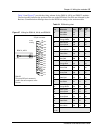
Appendix B, “Media bay module combinations,” on page 247 contains a blank table to use
if you changed the start DN on your system.
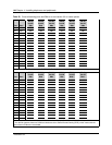
Double density: If a DS30 bus is set to double density, a second level of DNs and ports
become available, allowing 32 digital or analog telephones on a DS30 bus. On a default
system, bus 06 and 07 are set to Partial Double Density (PDD), and only the first level is
available to digital telephones. The second level remains designated as B2 channels, which
allows Companion to still be used on these two bus blocks. When the system is set to Full
Double Density, then all DS30 bus blocks have 32 B1 channels. In a FDD system,
Companion is not support.
Also, note on the tables below that DN numbering differs between systems that were
upgraded from BCM 2.5 software and systems that were new with BCM 3.0 or newer
software.