


122 Chapter 9 Starting the system
P0609324 01
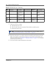
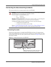
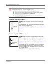
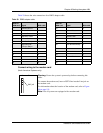
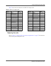
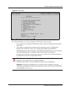
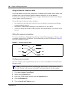
Table 30 shows the wire connections for a RS-422/EIA 530 modem adapter cable
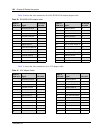
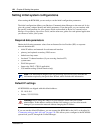
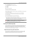
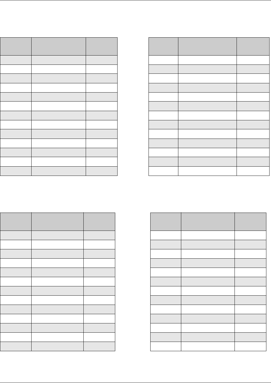
Table 31 shows the wire connections for a V.35 adapter cable.
Table 30 RS-422/EIA 530 adapter cable
DB26 on
WAN card
Signal
RS-422/EIA
530 cable
DB26 on
WAN card
Signal
RS-422/EIA
530 cable
1 Protective Ground 1 14 Transmit Data B 14
2 Transmit Data A 2
15 Transmit Clock A 15
3 Receive Data A 3 16 Receive Data B 16
4 Request to Send A 4
17 Receive Clock A 17
5 Clear to Send A 518 18
6 Data Set Ready A 6
19 Request To Send B 19
7 Signal Ground 7 20 Data Terminal Ready A 20
8 Data Carrier Detect A 8
21 21
9 Receive Clock B 9 22 Data Set Ready B 22
10 Data Carrier Detect B 10
23 Data Terminal Ready B 23
11 External Clock B 11 24 External Clock A 24
12 Transmit Clock B 12
25 25
13 Clear To Send B 13 26
Table 31 V.35 Adapter Cable
DB26 on
WAN card
Signal V.35 cable
DB26 on
WAN card
Signal V.35 cable
1 Protective Ground A 14 Transmit Data B S
2 Transmit Data A P
15 Transmit Clock A Y
3 Receive Data A R 16 Receive Data B T
4 Request to Send C
17 Receive Clock A V
5 Clear to Send D18
6 Data Set Ready E
19
7 Signal Ground B 20 Data Terminal Ready H
8 Data Carrier Detect F
21
9 Receive Clock B X22
10
23
11 External Clock B W 24 External Clock A U
12 Transmit Clock B AA
25
13 26