


154 Chapter 12 Installing Analog Terminal Adapters
P0609324 01
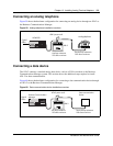
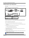
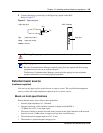
Testing insertion loss measurement
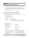
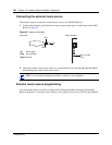
The maximum loss for ATA 2 to Central Office (CO) configuration, shown in Figure 64, must not
exceed 10 dB.
Figure 64 Insertion loss from the CO to the analog telephone
Measure the total insertion loss between the CO and analog device by using standard dial up test
lines with a transmission test set. For example, Hewlett-Packard 4935A Transmission Test Set.
For CO to analog device measurement
Use this procedure to measure the insertion loss from the CO to the analog device:
1 Establish a connection to the 1 mW, 1 kHz, CO service line with an analog telephone attached
to the ATA 2.
2 Ensure that the analog port terminates correctly in 600 ohms:
a Replace the analog telephone with the test set
b Use
RECEIVE/600 OHM/HOLD mode on the test set
3 Ensure that the test set connects in parallel to the service line before removing the analog
telephone or the line drops.
4 Remove the single-line telephone.
5 Measure the 1 kHz tone at the far end of the analog port, which is where the analog loop ends
and where the analog device connects.)
Longitudinal balance to ground 50 dB
60 to 4,000 Hz
With IEEE 455-1976 test
Overload level 3 dB
Note: The tone must be greater than - 10 dB (for example: - 9 dB is acceptable).
Analog telephone
ATA 2
BCM1000
Business Communications Manager to ATA 2
ATA 2 to Business Communications Manager
10 dB Max
Cable loss
Central Office
cable loss