


Chapter 10 Wiring the modules 135
Installation and Maintenance Guide
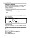
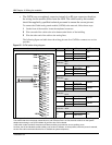
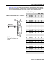
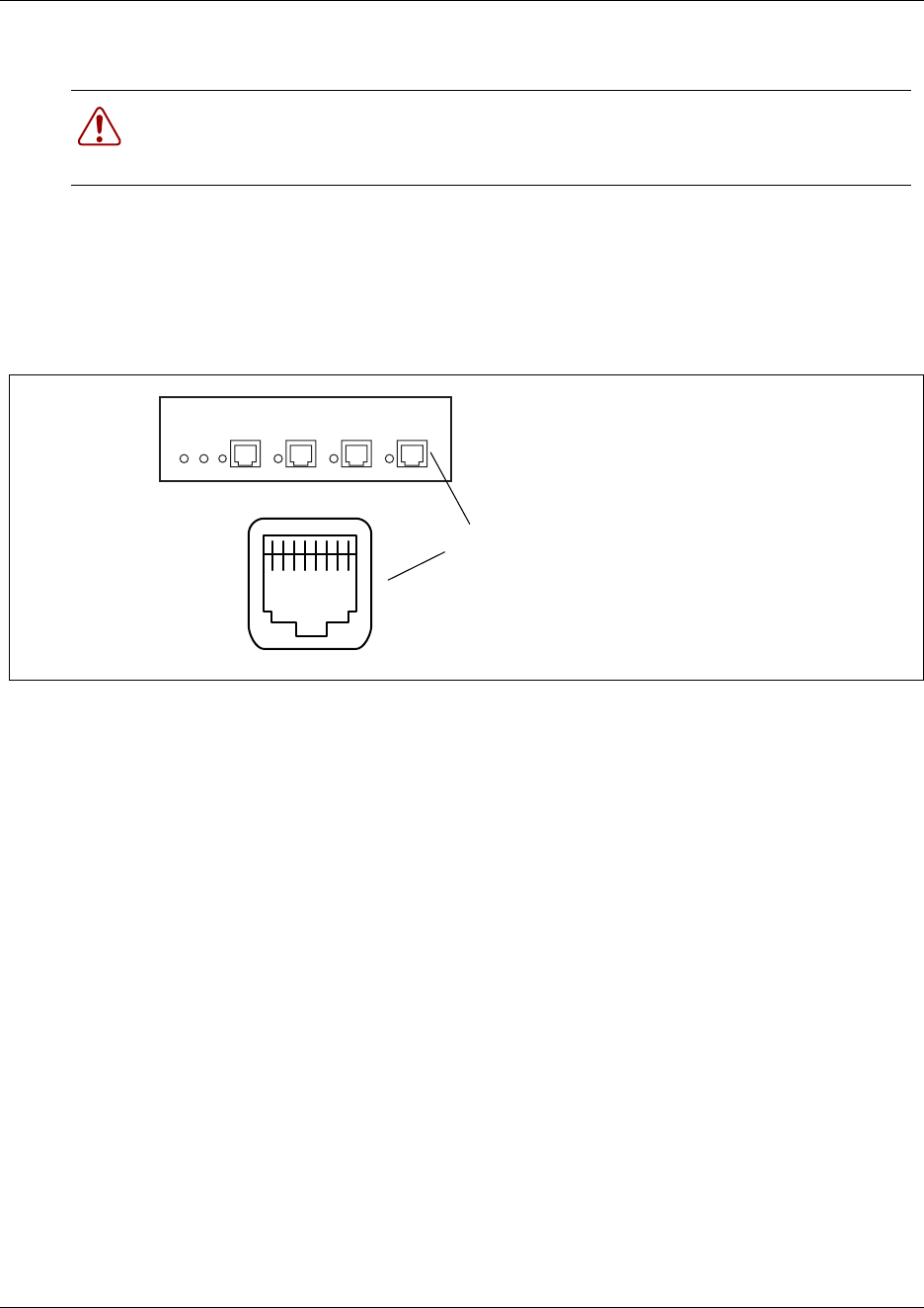
• Figure 56 shows the wiring pin-out for a BRI to the service provider (BRI loop set to T)
This diagram also applies to an S-Loop BRI, allowing connection to such S-Loop devices as
video phones, terminal adapters, and Grp 3 Fax machines. Note: the S-loop does not supply
supplementary power, such as required by video devices. Supplementary power must be
supplied by a separate power supply.
Figure 56 BRI RJ45 wiring array
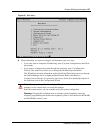
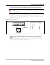
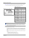
3 Insert the connector into the jack on the module.
4 You can now use the Unified Manager to configure the lines or sets associated with the
module.
Refer to the Business Communications Manager Programming Operations Guide for steps
about changing the default settings for each line/loop.
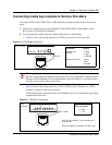
Warning: The BRI must only be connected to an NT1 provided by the service provider.
The NT1 must provide a Telecommunication Network Voltage (TNV) to Safety Extra
Low Voltage (SELV) barrier.
8 7 6 5 4 3 2 1
BRI connector
RJ45 sockets
Pin #/connection System side
1 not used
2 not used
3+RX
4 +TX
+TX
+RX
5- TX
6-RX
- RX
-TX
7 not used
8 not used