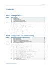
9.4.3 View and acknowledge alerts using ProLink III .............................................................156
9.4.4 View alarms using the Field Communicator ................................................................156
9.4.5 Alarm data in transmitter memory ..............................................................................157
9.5 Read totalizer and inventory values ...........................................................................................157
9.6 Start and stop totalizers and inventories ....................................................................................158
9.6.1 Start and stop totalizers and inventories using the display ..........................................158
9.7 Reset totalizers ..........................................................................................................................160
9.7.1 Reset totalizers using the display ................................................................................160
9.8 Reset inventories .......................................................................................................................161
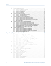
Chapter 10 Operate the transmitter with the Weights & Measures application ..............................163
10.1 Operate the transmitter when the Weights & Measures application is installed .........................163
10.1.1 Approved methods to read or obtain process data ......................................................164
10.1.2 Large totalizer values on the display (OIML applications only) .....................................164
10.1.3 Effect of the Weights & Measures application on process measurement and
outputs .......................................................................................................................165
10.1.4 Effect of the Weights & Measures application on operation and maintenance
functions ....................................................................................................................166
10.2 Switch between secured and unsecured mode ..........................................................................168
10.2.1 Switch between secured and unsecured mode using ProLink II ...................................169
10.2.2 Switch between secured and unsecured mode using ProLink III ..................................169
10.2.3 Switch between secured and unsecured mode using the switching utility ...................170
10.3 Clear Status Alarm A027: Security Breach ..................................................................................170
10.4 Replacing the core processor in a Weights & Measures installation ............................................171
Chapter 11 Measurement support .................................................................................................173
11.1 Options for measurement support ............................................................................................173
11.2 Use Smart Meter Verification .....................................................................................................173
11.2.1 Smart Meter Verification requirements .......................................................................174
11.2.2 Smart Meter Verification test preparation ...................................................................174
11.2.3 Run Smart Meter Verification ......................................................................................175
11.2.4 View test data .............................................................................................................179
11.2.5 Schedule automatic execution of the Smart Meter Verification test ............................183
11.3 Zero the flowmeter ...................................................................................................................186
11.3.1 Zero the flowmeter using the display ..........................................................................187
11.3.2 Zero the flowmeter using ProLink II .............................................................................188
11.3.3 Zero the flowmeter using ProLink III ............................................................................189
11.3.4 Zero the flowmeter using the Field Communicator .....................................................191
11.4 Validate the meter .....................................................................................................................192
11.4.1 Alternate method for calculating the meter factor for volume flow .............................193
11.5 Perform a (standard) D1 and D2 density calibration ...................................................................194
11.5.1 Perform a D1 and D2 density calibration using ProLink II .............................................194
11.5.2 Perform a D1 and D2 density calibration using ProLink III ............................................196
11.5.3 Perform a D1 and D2 density calibration using the Field Communicator .....................197
11.6 Perform a D3 and D4 density calibration (T-Series sensors only) ................................................199
11.6.1 Perform a D3 or D3 and D4 density calibration using ProLink II ....................................199
11.6.2 Perform a D3 or D3 and D4 density calibration using ProLink III ...................................200
11.6.3 Perform a D3 or D3 and D4 density calibration using the Field Communicator ............201
11.7 Perform temperature calibration ...............................................................................................203
Chapter 12 Troubleshooting ..........................................................................................................207
12.1 Status LED states .......................................................................................................................208
12.2 Status alarms .............................................................................................................................208
Contents
iv Micro Motion
®
Model 2700 Transmitters with Analog Outputs


