


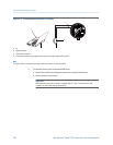
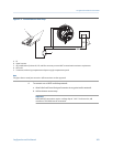
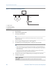
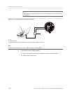
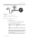
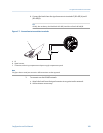
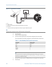
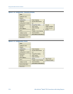
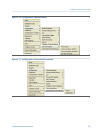
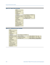
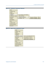
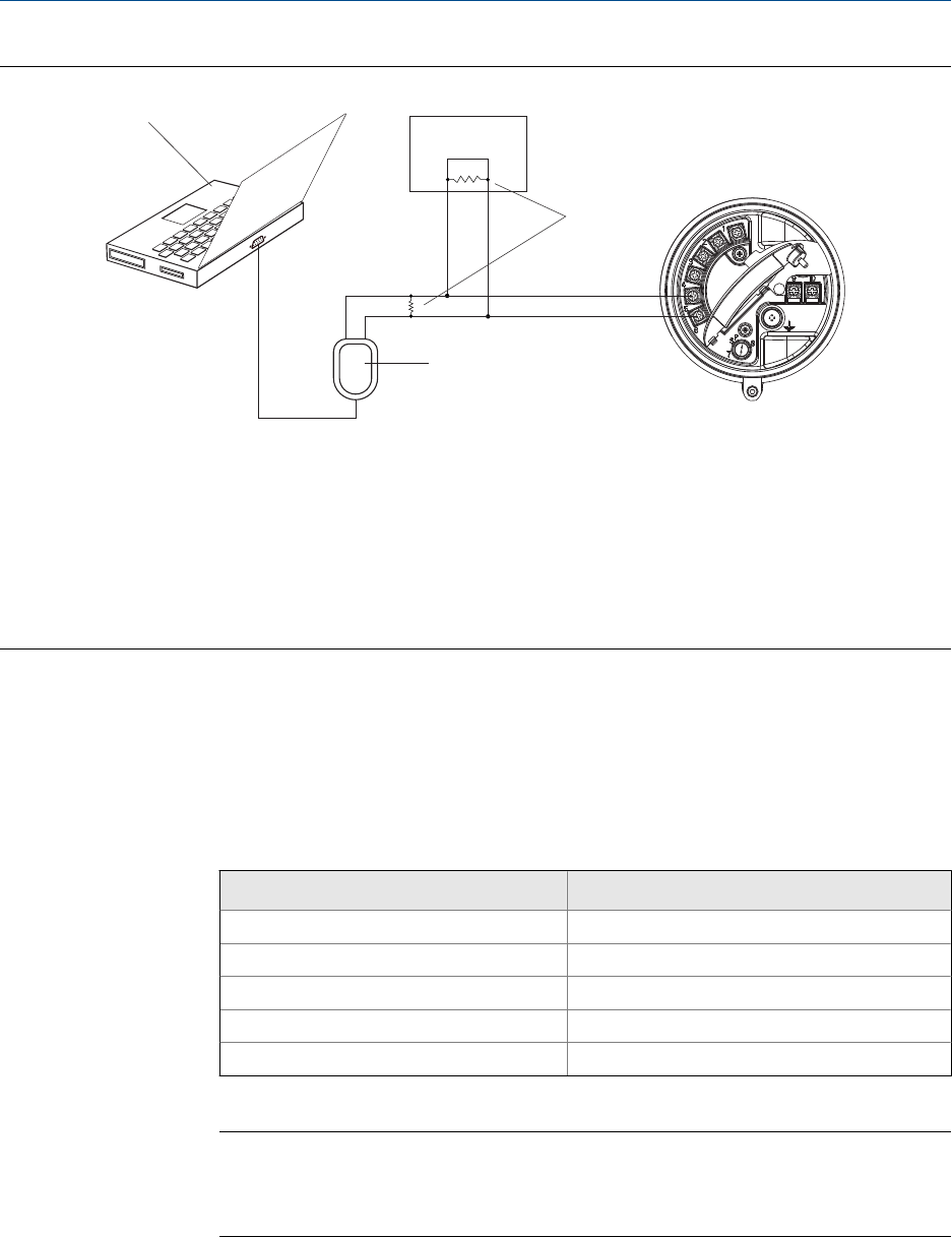
Connection over networkFigure C-8:
A
C
E
D
B
A. PC
B.
Signal converter
C.
120-
Ω
, 1/2-watt resistors at both ends of the segment, if necessary
D. DCS or PLC
E. Transmitter, with wiring compartment and power supply compartment opened
Note
This figure shows a serial port connection. USB connections are also supported.
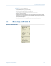
4. Start ProLink III.
5.
Choose Connect to Physical Device.
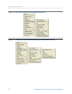
6. Set the connection parameters to the values configured in the transmitter.
If your transmitter has not been configured, use the default values shown here.
Default Modbus/RS-485 connection parametersTable C-2:
Parameter Default value
Protocol Modbus RTU
Baud 9600
Parity Odd
Stop Bits 1
Address 1
Tip
If you do not know the transmitter’s RS-485 communication settings, you can connect
through the service port, which always uses default settings, or use another communications
tool to view or change the settings.
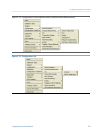
7. Set the PC Port value to the PC COM port that you are using for this connection.
8.
Click Connect.
Using ProLink III with the transmitter
310 Micro Motion
®
Model 2700 Transmitters with Analog Outputs