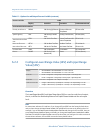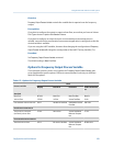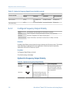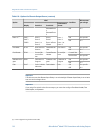
Options for Frequency Output Process Variable (continued)Table 6-5:
Process variable
Label
Display ProLink II ProLink III Field Communica-
tor
Net mass flow
NET M ED: Net Mass Flow
Rate
Net Mass Flow Rate ED Net Mass flo
Net volume flow
NET V ED: Net Vol Flow Rate Net Volume Flow Rate ED Net Vol flo
6.3.2 Configure Frequency Output Polarity
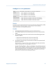
Display OFF-LINE MAINT > OFF-LINE CONFG > IO > CH B > SET FO > FO POLAR
ProLink II ProLink > Configuration > Frequency/Discrete Output > Frequency > Freq Output Polarity
ProLink III Device Tools > Configuration > I/O > Outputs > Frequency Output
Field Communicator Configure > Manual Setup > Inputs/Outputs > Frequency Output > FO Settings > FO Polarity
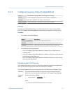
Overview
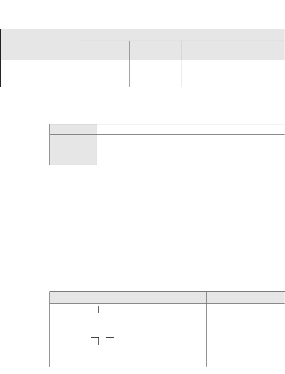
Frequency Output Polarity controls how the output indicates the ON (active) state. The default
value, Active High, is appropriate for most applications. Active Low may be required by
applications that use low-frequency signals.
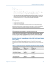
Procedure
Set Frequency Output Polarity as desired.
The default setting is Active High.
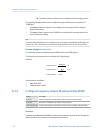
Options for Frequency Output Polarity
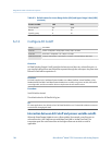
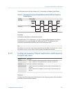
Options for Frequency Output PolarityTable 6-6:
Polarity Reference voltage (OFF) Pulse voltage (ON)
Active High
0 As determined by power sup-
ply, pull-up resistor, and load
(see the installation manual for
your transmitter)
Active Low
As determined by power sup-
ply, pull-up resistor, and load
(see the installation manual for
your transmitter)
0
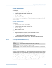
Integrate the meter with the control system
110 Micro Motion
®
Model 2700 Transmitters with Analog Outputs


