


• In general, lower damping values are preferable because there is less chance of data loss, and less
lag time between the actual measurement and the reported value.
• For gas applications, Micro Motion recommends setting Flow Damping to 2.56 or higher.
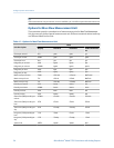
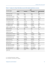
The value you enter is automatically rounded down to the nearest valid value. Valid
damping values are shown in the following table.
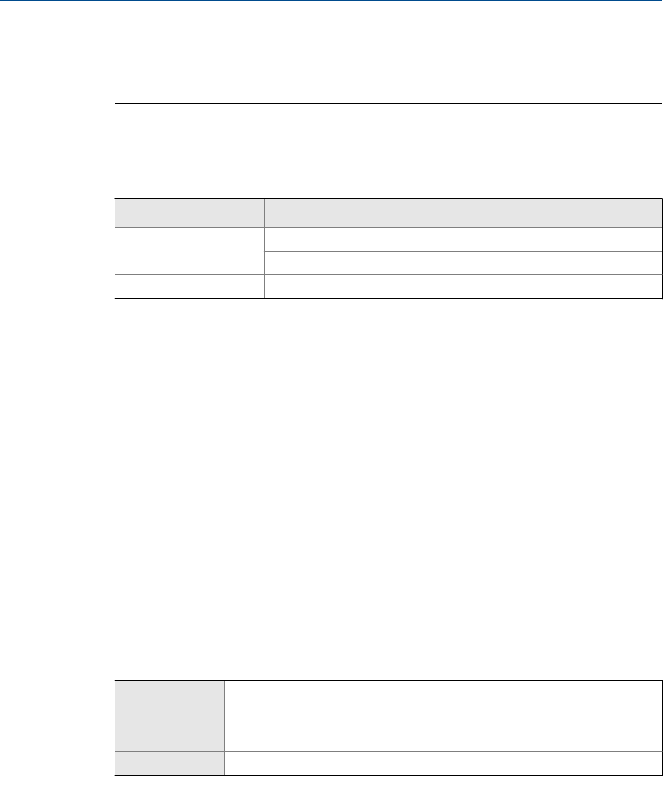
Valid values for Flow DampingTable 4-2:
Core processor type
Update Rate setting
Valid damping values
Standard
Normal
0, 0.2, 0.4, 0.8, ... 51.2
Special
0, 0.04, 0.08, 0.16, ... 10.24
Enhanced Not applicable 0, 0.2, 0.4, 0.8, ... 51.2
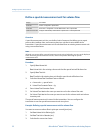
Effect of Flow Damping on volume measurement
Flow Damping affects volume measurement for liquid volume data. Flow Damping also affects
volume measurement for gas standard volume data. The transmitter calculates volume
data from the damped mass flow data.
Interaction between Flow Damping and Added Damping
In some circumstances, both Flow Damping and Added Damping are applied to the reported
mass flow value.
Flow Damping controls the rate of change in flow process variables. Added Damping controls
the rate of change reported via the mA output. If mA Output Process Variable is set to Mass
Flow Rate, and both Flow Damping and Added Damping are set to non-zero values, flow
damping is applied first, and the added damping calculation is applied to the result of the
first calculation.
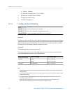
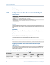
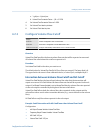
4.1.3 Configure Mass Flow Cutoff
Display
Not available
ProLink II ProLink > Configuration > Flow > Mass Flow Cutoff
ProLink III Device Tools > Configuration > Process Measurement > Flow
Field Communicator Configure > Manual Setup > Measurements > Flow > Mass Flow Cutoff
Overview
Mass Flow Cutoff specifies the lowest mass flow rate that will be reported as measured. All
mass flow rates below this cutoff will be reported as 0.
Configure process measurement
Configuration and Use Manual 27