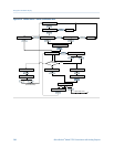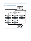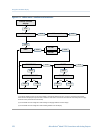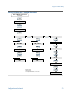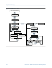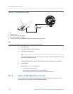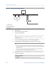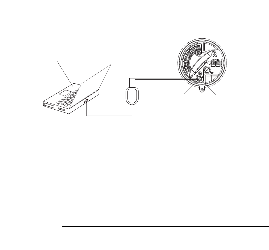
Connection to service portFigure B-1:
A
C D
E
B
A. PC
B.
Signal converter
C. Service port terminal 7 (RS-485/A)
D. Service port terminal 8 (RS-485/B)
E. Transmitter, with wiring compartment and power supply compartment opened
Note
This figure shows a serial port connection. USB connections are also supported.
4. Start ProLink II.
5.
Choose Connection > Connect to Device.
6. Set Protocol to Service Port.
Tip
Service port connections use standard connection parameters and a standard address. You do
not need to configure them here.
7. Set the COM Port value to the PC COM port that you are using for this connection.
8.
Click Connect.
Need help? If an error message appears:
• Switch the leads and try again.
• Ensure that you have specified the correct COM port.
• Check the physical connection between the PC and the transmitter.
B.2.3 Make a HART/Bell 202 connection
You can connect directly to the mA terminals on the transmitter, to any point in a local
HART loop, or to any point in a HART multidrop network.
Using ProLink II with the transmitter
276 Micro Motion
®
Model 2700 Transmitters with Analog Outputs


