Procedure
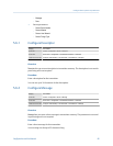
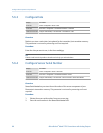
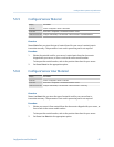
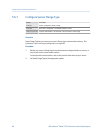
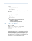
Set LRV and URV as desired.
• LRV is the value of mA Output Process Variable represented by an output of 4 mA. The
default value for LRV depends on the setting of mA Output Process Variable. Enter LRV in
the measurement units that are configured for mA Output Process Variable.
• URV is the value of mA Output Process Variable represented by an output of 20 mA. The
default value for URV depends on the setting of mA Output Process Variable. Enter URV in
the measurement units that are configured for mA Output Process Variable.
Tips
For best performance:
• Set LRV ≥ LSL (lower sensor limit).
• Set URV ≤ USL (upper sensor limit).
• Set these values so that the difference between URV and LRV is ≥ Min Span (minimum span).
Defining URV and LRV within the recommended values for Min Span, LSL, and USL ensures that the
resolution of the mA output signal is within range of the bit precision of the D/A converter.
Note
You can set URV below LRV. For example, you can set URV to 50 and LRV to 100.
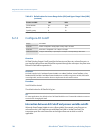
The mA output uses a range of 4–20 mA to represent mA Output Process Variable. Between
LRV and URV, the mA output is linear with the process variable. If the process variable
drops below LRV or rises above URV, the transmitter posts an output saturation alarm.
Default values for Lower Range Value (LRV) and Upper Range
Value (URV)
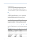
Each option for mA Output Process Variable has its own LRV and URV. If you change the
configuration of mA Output Process Variable, the corresponding LRV and URV are loaded and
used.
Default values for Lower Range Value (LRV) and Upper Range Value (URV)Table 6-2:
Process variable LRV URV
All mass flow variables –200.000 g/sec 200.000 g/sec
All liquid volume flow variables –0.200 l/sec 0.200 l/sec
All density variables 0.000 g/cm
3
10.000 g/cm
3
All temperature variables –240.000 °C 450.000 °C
Drive gain 0.00% 100.00%
Gas standard volume flow –423.78 SCFM 423.78 SCFM
External temperature –240.000 °C 450.000 °C
External pressure 0.000 bar 100.000 bar
Integrate the meter with the control system
Configuration and Use Manual 103


