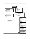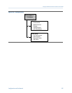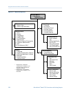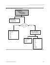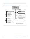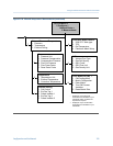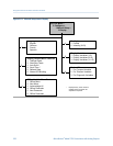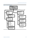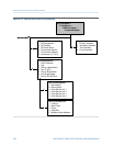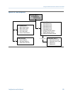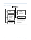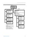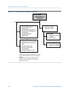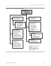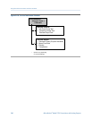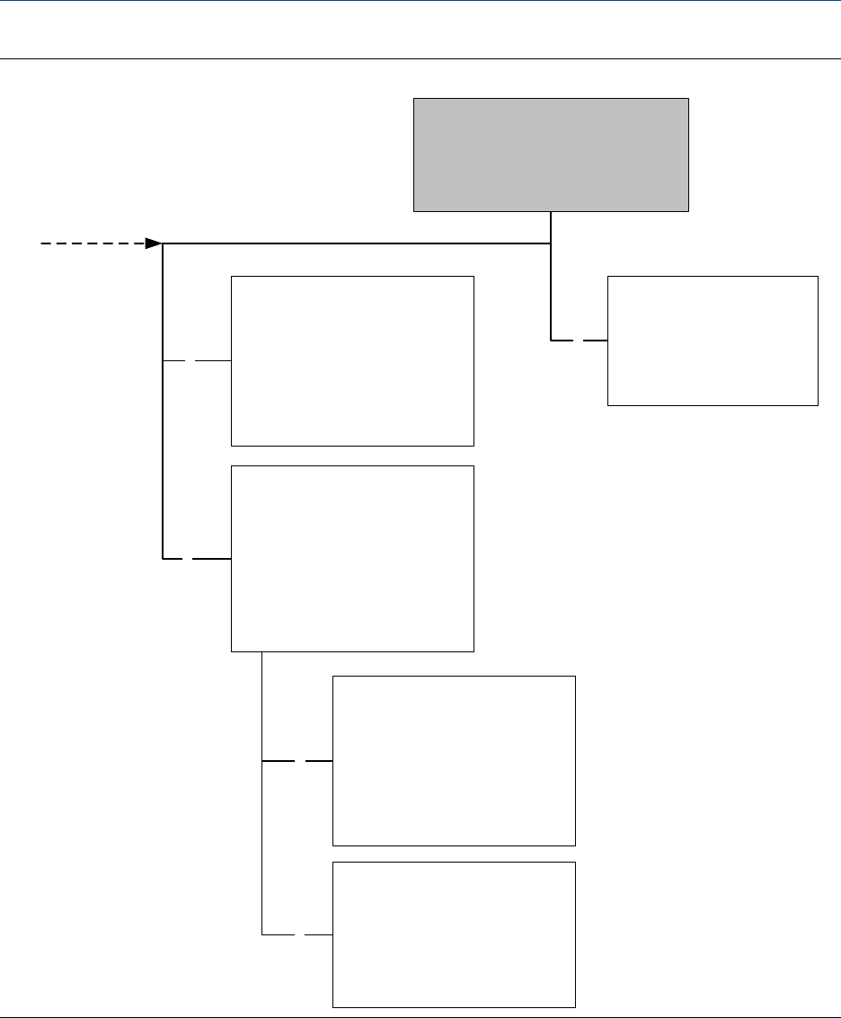
Manual Setup menu: I/O (continued)Figure D-13:
Discrete Output
1 DO Assignment
2 DO Polarity
3 DO Fault Action
4 Flow Switch Source
5 Flow Switch Setpoint
6 Hysteresis (0.1-10.0)
4
6
Map Variables
1 Primary Variable
2 Secondary Variable
3 Third Variable
4 Fourth Variable
5
Communications
1 HART Address
2 Tag
3 Device Identification
4 Dev ID (CP)
5 Set Up Burst Mode
6 mA Output Mode
7 Set Up RS-485 Port
Set Up Burst Mode
1 Burst Mode
2 Burst Option
3 Field Device Var 1
4 Field Device Var 2
5 Field Device Var 3
6 Field Device Var 4
Set Up RS-485 Port
1 Protocol
2 Baud Rate
3 Parity
4 Stop Bits
5 Modbus Slave Address
7
5
On-Line Menu >
2 Configure >
1 Manual Setup >
4 Inputs/Outputs
Using the Field Communicator with the transmitter
334 Micro Motion
®
Model 2700 Transmitters with Analog Outputs


