


a. Leave the terminal blocks disconnected.
b. Remove the lid of the junction box.
c. Testing one terminal at a time, place a DMM lead on the terminal and the other
lead on the sensor case.
With the DMM set to its highest range, there should be infinite resistance on
each lead. If there is any resistance at all, there is a short to case.
6. Test the resistance of junction box terminal pairs.
a. Test the brown terminal against all other terminals except the red one.
b. Test the red terminal against all other terminals except the brown one.
c. Test the green terminal against all other terminals except the white one.
d. Test the white terminal against all other terminals except the green one.
e. Test the blue terminal against all other terminals except the gray one.
f. Test the gray terminal against all other terminals except the blue one.
g. Test the orange terminal against all other terminals except the yellow and violet
ones.
h. Test the yellow terminal against all other terminals except the orange and violet
ones.
i. Test the violet terminal against all other terminals except the yellow and orange
ones.
There should be infinite resistance for each pair. If there is any resistance at all, there
is a short between terminals.
Postrequisites
To return to normal operation:
1. Plug the terminal blocks into the terminal board.
2. Replace the end-cap on the core processor housing.
3. Replace the lid on the sensor junction box.
Important
When reassembling the meter components, be sure to grease all O-rings.
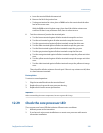
12.29 Check the core processor LED
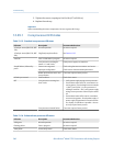
The core processor has an LED that indicates different meter conditions.
1. Maintain power to the transmitter.
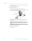
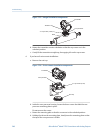
2. If you have a 4-wire remote installation or a remote core processor with remote
transmitter installation:
Troubleshooting
Configuration and Use Manual 243