


2-11
2
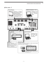
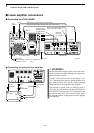
INSTALLATION AND CONNECTIONS
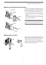
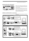
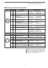
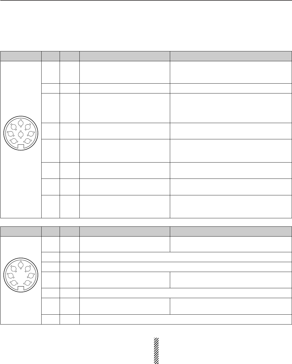
■ Accessory connector information
ACC 2
PIN No.
NAME DESCRIPTION SPECIFICATIONS
ACC 1
PIN No.
NAME DESCRIPTION SPECIFICATIONS
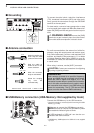
NOTE: If the CW side tone level limit or beep level
limit is in use, the CW side tone or beep tone de-
creases from the fixed level when the [AF] control is
rotated above a specified level. (p. 12-6)
1
2
3
4
5
6
7
8
“High” level : More than 2.4 V
1RTTY Controls RTTY keying “Low” level : Less than 0.6 V
Output current : Less than 2 mA
2 GND Connects to ground. Connected in parallel with ACC 2 pin 2.
Input/output pin.
Ground level : –0.5 V to 0.8 V
3 SEND Goes to ground when transmitting.
Output current : Less than 20 mA
When grounded, transmits.
Input current (Tx) : Less than 200 mA
Connected in parallel with ACC 2 pin 3.
4 MOD
Modulator input. Input impedance : 10 kΩ
Connects to a modulator. Input level : Approx. 100 mV rms
AF detector output.
Output impedance : 4.7 kΩ
5AFFixed, regardless of [AF] position
Output level : 100–300 mV rms
in default settings. (see notes below)
6 SQLS
Squelch output. SQL open : Less than 0.3 V/5 mA
Goes to ground when squelch opens.
SQL closed : More than 6.0 V/100 µA
7 13.8 V 13.8 V output when power is ON.
Output current : Max. 1 A
Connected in parallel with ACC 2 pin 7.
Control voltage : –4 V to 0 V
8 ALC ALC voltage input. Input impedance : More than 10 kΩ
Connected in parallel with ACC 2 pin 5.
18VRegulated 8 V output.
Output voltage : 8 V ±0.3 V
Output current : Less than 10 mA
2 GND Same as ACC 1 pin 2.
3 SEND Same as ACC 1 pin 3.
4 BAND
Band voltage output.
Output voltage : 0 to 8.0 V
(Varies with amateur band)
5 ALC Same as ACC 1 pin 8.
6TRV
Activates [X-VERTER] input/output Input impedance : More than 10 kΩ
when “HIGH” voltage is applied. Input voltage : 2 to 13.8 V
7
13.8 V
Same as ACC 1 pin 7.
1
2
3
4
5
6
7