


DD
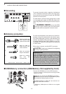
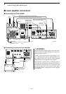
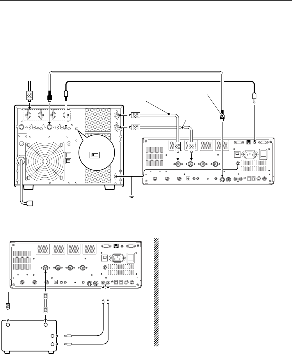
Connecting a non-Icom linear amplifier
R WARNING:
Set the transceiver output power and linear ampli-
fier ALC output level after referring to the linear am-
plifier instruction manual.
The ALC input level must be in the range 0 V to
–4 V. The transceiver does not accept positive volt-
age. Non-matched ALC and RF power settings
could overheat or damage the linear amplifier.
The maximum signal level of [RELAY] jack is
16 V/0.5 A DC with initial setting, and 250 V/200 mA
with “MOSFET” setting (see p. 12-8 for details). Use
an external relay unit if your non-Icom linear ampli-
fier requires control voltage and/or current greater
than specified.
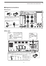
■ Linear amplifier connections
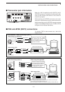
DD
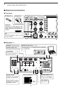
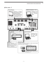
Connecting the IC-PW1/EURO
2-8
2
INSTALLATION AND CONNECTIONS
RF OUTPUT RF INPUT
SEND
ALC
50 Ω
coaxial cable
TransceiverANT1
ALC
RELAY
To an
antenna
Non-Icom linear amplifier
To an
antenna
ACC-1
ANT
ANT2
ANT1
ACC 2
INPUT1
INPUT2
REMOTE
EXCITER
1
1&2
GND
GND
IC-PW1/EURO
AC outlet
(Non-European versions: 100–120/220–240 V
European version : 230 V)
Ground
Transceiver
REMOTE
Remote control cable (supplied with the IC-PW1/EURO)
ACC cable (supplied with the IC-PW1/EURO)
Be sure to connect the cable
to the 7-pin ACC 2 jack.
Coaxial cable
(supplied with the
IC-PW1/EURO)
Coaxial cable*
*Optional
Connect
[INPUT2]
if necessary