


2-2
■ Unpacking
After unpacking, immediately report any damage to the
delivering carrier or dealer. Keep the shipping cartons.
For a description and a diagram of accessory equip-
ment included with the IC-7700, see ‘Supplied acces-
sories’ on p. iii of this manual.
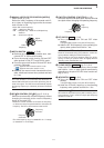
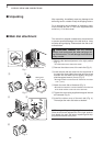
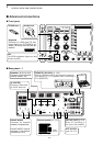
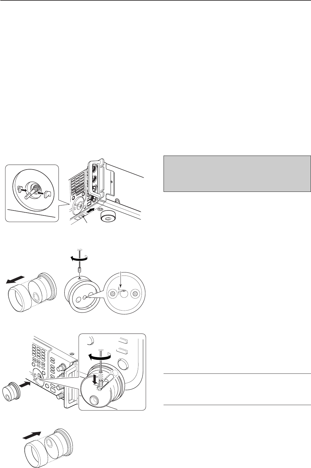
■ Main dial attachment
The main dial is shipped unattached to the transceiver
to prevent possible damage to the dial shaft or rotary
encoder during shipping. Please attach the dial as de-
scribed below.
q Slide the dial brake adjustment to the right position
(Fig. 1).
• The dial brakes move inward as shown.
w Remove the rubber cover of the main dial (Fig. 2).
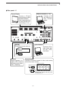
e Insert the main dial set-screw into the screw hole of
the main dial, then tighten the screw until the screw
extends into the shaft hole out slightly using sup-
plied hexagonal wrench (2 mm) (Fig. 2).
• Be careful that the screw does not extend out more than
1 mm (
1
/32 in).
r Attach the main dial as illustrated (Fig. 3).
• Be careful to match the correct orientation of the flat face
of the shaft and the screw hole of the dial knob.
t Tighten the screw using supplied hexagonal wrench
as illustrated (Fig. 3).
y Install the rubber cover of the main dial (Fig. 4).
Then adjust the main dial brake as desired.
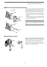
✔
When re-packing and shipping the transceiver:
Slide the dial brake adjustment to the right position,
then detach the main dial when re-packing and ship-
ping the transceiver at any time.
2
INSTALLATION AND CONNECTIONS
Dial brake adjustment
Fig. 1
q
Shorter than
1 mm (
1
/32 in)
Fig. 2
e
w
Fig. 3
rt
RR
CAUTION!: NEVER hold any controller
knob(s), such as the main dial, when carrying or lift-
ing the transceiver. This will damage the dial shaft or
rotary encoder.
Fig. 4
y