


14-2
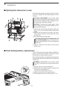
■ Remote jack (CI-V) information
DD
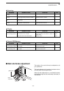
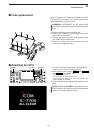
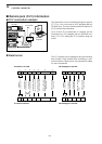
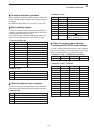
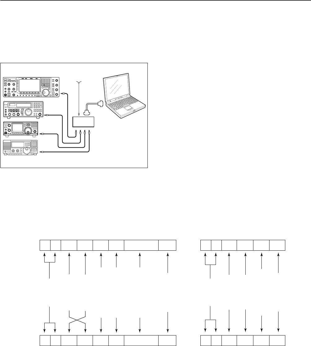
CI-V connection example
The transceiver can be connected through an optional
CT-17 CI-V LEVEL CONVERTER to a PC equipped with an
RS-232C port. The Icom Communications Interface-V
(CI-V) controls the transceiver.
Up to 4 Icom CI-V transceivers or receivers can be
connected to a PC equipped with an RS-232C port.
See p. 12-17 for setting the CI-V condition using set
mode.
DD
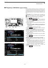
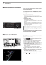
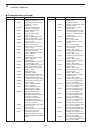
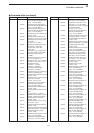
Data format
The CI-V system can be operated using the following
data formats. Data formats differ according to com-
mand numbers. A data area or sub command is added
for some commands.
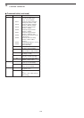
Controller to IC-7700
FE FE 74 E0 Cn Sc Data area FD
Preamble
code (fixed)
Transceiver’s
default address
Controller’s
default address
Command number
(see the command table)
Sub command number
(see command table)
BCD code data for
frequency or memory
number entry
End of message
code (fixed)
OK message to controller
FE FE E0 74 FB FD
FE FE E0 74 FA FD
Preamble
code (fixed)
Controller’s
default address
Transceiver’s
default address
OK code
(fixed)
End of message
code (fixed)
NG message to controller
NG code
(fixed)
IC-7700 to controller
qwert y u
FE FE E0 74 Cn Sc Data area FD
qwert y u
personal
computer
ct- 17
IC-7700
9–15 V DC
mini-plug cable
14
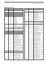
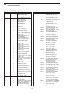
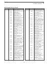
CONTROL COMMAND