


14-3
DD
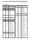
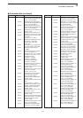
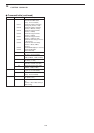
Command table
14
CONTROL COMMAND
00 — Send frequency data
01 Same as Send mode data
command 06
02 — Read band edge frequencies
03 — Read operating frequency
04 — Read operating mode
05 — Set operating frequency
06 00 Select LSB
01 Select USB
02 Select AM
03 Select CW
04 Select RTTY
05 Select FM
07 Select CW-R
08 Select RTTY-R
12 Select PSK
13 Select PSK-R
07 — Select VFO mode
00 Select VFO-A
01 Select VFO-B
A0 Equalize VFO-A and VFO-B
B0 Exchange VFO-A and VFO-B
08 — Select memory mode
0001–0101* Select memory channel
*P1=0100, P2=0101
09 — Memory write
0A — Memory to VFO
0B — Memory clear
0E 00 Scan stop
01 Programmed/memory scan start
02 Programmed scan start
03 ∂F scan start
12 Fine programmed scan start
13 Fine ∂F scan start
22 Memory scan start
23 Select memory scan start
A1–A7 Set ∂F scan span (A1=±5 kHz;
A2=±10 kHz; A3=±20 kHz;
A4=±50 kHz; A5=±100 kHz;
A6=±500 kHz; A7=±1 MHz)
B0 Set as non-select channel
B1 Set as select channel
(1=★1; 2=★2; 3=★3; when no
data command is specified, the
previously set number or “★1” is
selected)
B2 Set the number for select memory
scan (0=ALL; 1=★1; 2=★2; 3=★3)
D0 Set scan resume OFF
D3 Set scan resume ON
0F 00 Turn the split function OFF
01 Turn the split function ON
10 00 Select 10 Hz (1 Hz) tuning step
01 Select 100 Hz tuning step
02 Select 1 kHz tuning step
03 Select 5 kHz tuning step
04 Select 9 kHz tuning step
05 Select 10 kHz tuning step
06 Select 12.5 kHz tuning step
07 Select 20 kHz tuning step
08 Select 25 kHz tuning step
11 — Select/read attenuator
(0=OFF; 1=6 dB; 2=12 dB;
3=18 dB)
12 00 + RX ANT Select/read ANT1 selection
(00=RX ANT OFF;
01=RX ANT ON)
01 + RX ANT Select/read ANT2 selection
(00=RX ANT OFF;
01=RX ANT ON)
02 + RX ANT Select/read ANT3 selection
(00=RX ANT OFF;
01=RX ANT ON)
03 + RX ANT Select/read ANT4 selection
(00=RX ANT OFF;
01=RX ANT ON)
13 00 Announce with voice synthesizer
01 (00=all data; 01=frequency and
02 S-meter level; 02=receive mode)
14 01 + Level data [AF] level setting
(0=max. CCW to 255=max. CW)
02 + Level data [RF] level setting
(0=max. CCW to 255=11 o’clock)
03 + Level data [SQL] level setting
(0=11 o’clock to 255=max. CW)
05 + Level data [APF] level setting
(0=Pitch–550 Hz, 128=Pitch,
255=Pitch+550 Hz; 10 Hz steps)
06 + Level data [NR] level setting
(0=min. to 255=max.)
07 + Level data Inside [TWIN PBT] setting or IF
shift setting (0=max. CCW,
128=center, 255=max. CW)
08 + Level data Outside [TWIN PBT] setting
(0=max. CCW, 128=center,
255=max. CW)
09 + Level data [CW PITCH] setting
(0=300 Hz, 128=600 Hz,
255=900 Hz; 5 Hz steps)
0A + Level data [RF POWER] setting (0=max.
CCW to 255=max. CW)
0B + Level data [MIC] setting (0=max. CCW to
255=max. CW)
0C + Level data [KEY SPEED] setting (0=max.
CCW to 255=max. CW)
0D + Level data [NOTCH] setting
(0=low freq. to 255=high freq.)
0E + Level data [COMP] setting
(0=max. CCW to 255=max. CW)
0F + Level data [DELAY] setting
(0=max. CCW to 255=max. CW)
11 + Level data [AGC] control setting
(0=max. CCW to 255=max. CW)
12 + Level data [NB] control setting
(0=max. CCW to 255=max. CW)
13 + Level data [DIGI-SEL] setting
(0=max. CCW to 255=max. CW)
14 + Level data [DRIVE] setting
(0=max. CCW to 255=max. CW)
15 + Level data [MONI GAIN] setting (0=max.
CCW to 255=max. CW)
16 + Level data [VOX GAIN] setting (0=max.
CCW to 255=max. CW)
17 + Level data [ANTI VOX] setting
(0=max. CCW to 255=max. CW)
Command Sub command Description Command Sub command Description