


2-4
2
INSTALLATION AND CONNECTIONS
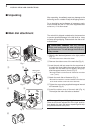
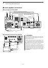
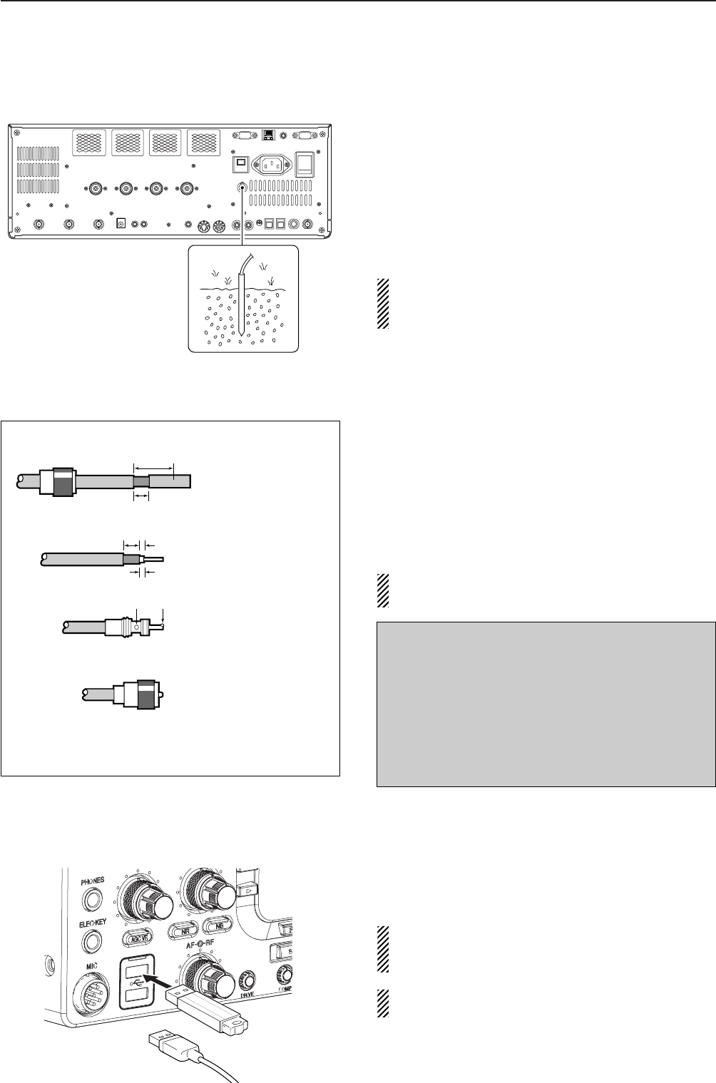
■ Grounding
To prevent electrical shock, television interference
(TVI), broadcast interference (BCI) and other prob-
lems, ground the transceiver through the GROUND
terminal on the rear panel.
For best results, connect a heavy gauge wire or strap
to a long earth-sunk copper rod. Make the distance be-
tween the [GND] terminal and ground as short as pos-
sible.
R WARNING: NEVER connect the [GND]
terminal to a gas or electric pipe, since the connec-
tion could cause an explosion or electric shock.
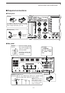
■ Antenna connection
For radio communications, the antenna is of critical im-
portance, along with output power and receiver sensi-
tivity. Select antenna(s), such as a well-matched 50 Ω
antenna, and feedline. We recommend 1.5:1 or better
of Voltage Standing Wave Ratio (VSWR) for your de-
sired band. Of course, the transmission line should be
a coaxial cable.
When using 1 antenna, use the [ANT1] connector.
CAUTION: Protect your transceiver from lightning
by using a lightning arrestor.
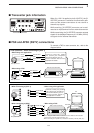
■ USB-Memory connection (USB-Memory: Not supplied by Icom)
Connect the USB-Memory* to the USB connector.
• Unmount operation is necessary before removing the USB-
Memory* (p.12-25).
Make sure to connect the USB-Memory correctly.
NEVER connect or remove the USB-Memory when
the read/write indicator lights or blinks.
A USB keyboard* or USB hub* can also be con-
nected to the USB connector.
*: USB-Memory, USB keyboard or USB hub is not supplied
by Icom.
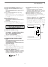
Antenna SWR
Each antenna is tuned for a specified frequency
range and SWR may be increased out-of-range.
When the SWR is higher than approx. 2.0:1, the
transceiver’s power drops to protect the final transis-
tors. In this case, an antenna tuner is useful to match
the transceiver and antenna. Low SWR allows full
power for transmitting. The IC-7700 has an SWR
meter to monitor the antenna SWR continuously.
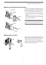
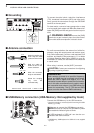
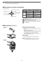
PL-259 CONNECTOR INSTALLATION EXAMPLE
30 mm ≈
9
⁄8 in 10 mm ≈
3
⁄8 in 1–2 mm ≈
1
⁄16 in
30 mm
10 mm (soft solder)
10 mm
1–2 mm
solder solder
Soft
solder
Coupling ring
Slide the coupling ring
down. Strip the cable
jacket and in the braid.
Slide the connector
body on and solder it.
Screw the coupling
ring onto the
connector body.
Strip the cable as
shown at left. Tin the
center conductor.
q
w
e
r
or