


1-10
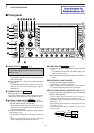
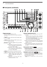
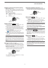
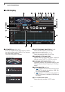
^1 PASSBAND TUNING CONTROLS [TWIN-PBT]
(p. 5-12)
Adjusts the receiver’s IF filter “passband width” via
the DSP.
• Passband width and shift frequency are displayed in the
multi-function display.
• Push and hold for 1 sec. to clear the PBT
settings.
• Adjustment range is set to half of the IF filter passband
width. 25 Hz steps and 50 Hz steps are available.
✔
What is the PBT control?
The PBT function electronically modifies the IF passband
width to reject interference. This transceiver uses the
DSP circuit for the PBT function.
^2 PBT CLEAR SWITCH (p. 5-12)
Clears the PBT settings when pushed and held for
1 sec.
• The [PBT-CLR] indicator above this switch lights when
PBT is in use.
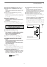
^3 DIGITAL RF SELECTOR SWITCH
(p. 5-18)
Turns the digital RF preselector ON and OFF.
• The [DIGI-SEL] indicator lights green when the prese-
lector is in use.
^4 DIGITAL RF SELECTOR CONTROL [DIGI-SEL]
(p. 5-18)
Adjusts the digital RF selector center frequency.
• The control can be reassigned as the audio peak filter
adjustment (p. 12-16)
DIGI-SEL
PBT-CLR
PBT-CLR
Higher
frequency
Lower
frequency
PBT1
PBT2
Low cutHigh cut Center
–+
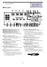
1
PANEL DESCRIPTION
SSB CW
RTTY/PSK
AM/FM DATA
AUTO
TUNE
LOCK
TS
XFC
M.SCOPE
EXIT/SET
REC
PLAY
VOICE MEMORYBRIGHTCONTRASTVOX GAINMONI GAINCOMPDRIVE ANTI VOX
DIGI-SEL NOTCH
RIT/∂TX
CW PITCH
TWIN-PBT
F-1 F-2 F-3 F-4 F-5 F-6 F-7
LOCKTX RX SPLIT
FILTER
PBT-CLR
DIGI-SEL
APF/TPF
NOTCH
RIT
CLEAR
SPEECH
1
1.8
2
3.5
3
7
4
10
5
14
6
18
7
21
8
24
MP-W MP-R
MW V/M
A/B A=B
9
28
GENE
0
50
ENT
F-INP
∂TX
SPLIT
&1 &0 ^9
^1
^2
^3
^4
^5
^6
^7
^8
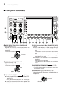
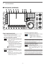
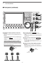
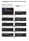
■ Front panel (continued)