


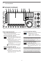
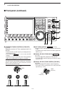
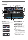
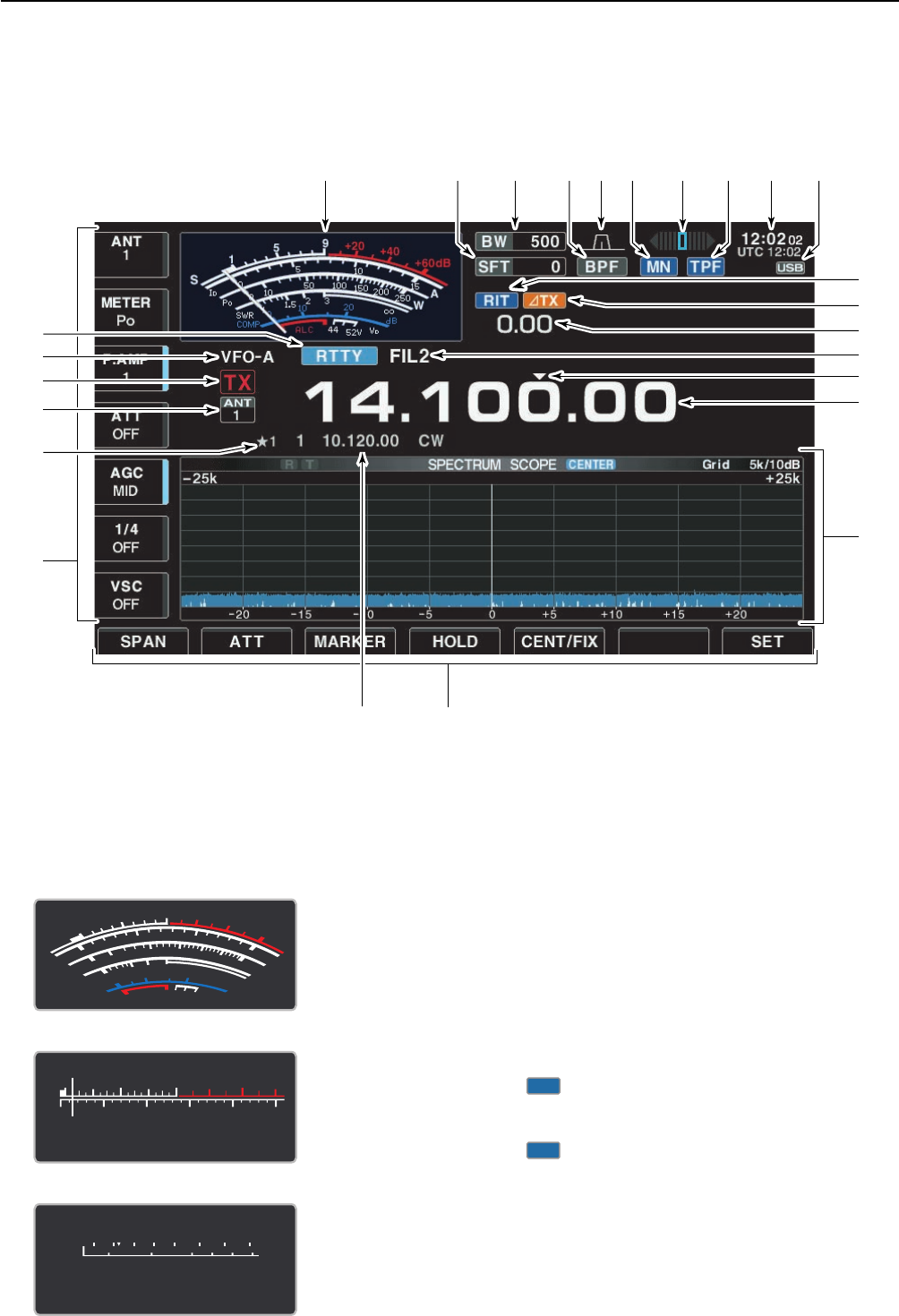
q S/RF METER (pgs. 3-10, 3-11)
Shows the signal strength while receiving. Shows
the relative output power, SWR, ALC or compres-
sion levels while transmitting.
•Atotal of 3 meter types are available.
w SHIFT FREQUENCY INDICATOR (p. 5-12)
Shows the shift frequency of the IF filter.
e BAND WIDTH INDICATOR (p. 5-12)
Shows the passband width of the IF filter.
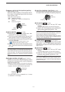
r BANDPASS FILTER INDICATOR
Appears when the narrow filter (500 Hz or less) is
selected during CW, RTTY or PSK31 operation.
t PASSBAND WIDTH INDICATOR (p. 5-12)
Graphically displays the passband width for twin
PBT operation and center frequency for IF shift op-
eration.
y NOTCH INDICATOR (p. 5-18)
➥ “” appears when the manual notch function
is in use. This function is available in SSB, CW,
RTTY, PSK and AM modes.
➥ “” appears when the auto notch function is
in use. This function is available in SSB, AM and
FM modes.
u RTTY TUNING INDICATOR
Shows the tuning condition in RTTY mode.
AN
MN
1-14
1
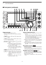
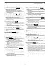
PANEL DESCRIPTION
qu
!1
!2
!4
!5
!6
oetwyri!0
!8
!9
@0
@2
@1
@3
@4
@5
!7
!3
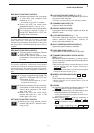
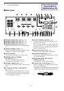
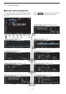
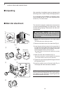
■ LCD display
S
Po
1357
9
250W200100 150500
+
20
+
40
+
60dB
S
Po
13579
250W200100 15050
0
10
+
20
+
40
+
60dB
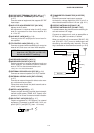
• Standard meter
• Edgewise meter
• Bar meter
S
1
0
0
0
1
2
5
10
10
10
20
44
52V
50 100
150
200
250
15
3
1.5
ID
VD
dB
W
A
Po
SWR
COMP
ALC
5
9
+
20
+
40
+
60dB
∞