


1-15
1
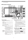
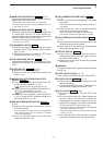
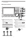
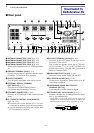
PANEL DESCRIPTION
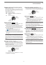
i APF/TPF INDICATOR
➥ “” appears when the audio peak filter func-
tion is in use. This function is available in CW
mode. (p. 4-6)
➥ “” appears when the twin peak filter function
is in use. This function is available in RTTY
mode. (p. 4-14)
o CLOCK READOUT
Shows the current time. Local and UTC time can be
indicated at the same time.
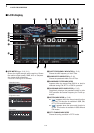
!0 USB-MEMORY INDICATOR
Appears when USB-Memory is connected and
blinks while reading or writing the USB-Memory.
!1 RIT INDICATOR
Appears when RIT function is in use.
!2
∂∂
TX INDICATOR
Appears when ∂TX function is in use.
!3 RIT/
∂∂
TX SHIFT FREQUENCY INDICATOR
Shows the shift frequency for the RIT or ∂TX func-
tion.
!4 IF FILTER INDICATOR (p. 5-13)
Shows the selected IF filter number.
!5 QUICK TUNING INDICATOR (p. 3-6)
Appears when the quick tuning step function is in use.
!6 FREQUENCY READOUTS
Shows the operating frequency.
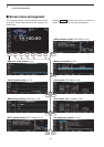
!7 MULTI-FUNCTION SCREEN
Shows the screens for the multi-function digital
meter, spectrum scope, voice recorder, memory list,
scan, memory keyer, RTTY decoder, PSK decoder,
IF filter selection or set modes, etc.
!8 LCD FUNCTION SWITCH GUIDE
Indicates the function of the LCD function switches
([F-1] – [F-7]).
!9 MEMORY CHANNEL READOUTS
➥ Shows the selected memory channel contents in
VFO mode.
➥ Shows the VFO contents in memory mode.
@0 MULTI-FUNCTION SWITCH GUIDE
Indicates the function of the multi-function switches.
@1 SELECT MEMORY CHANNEL INDICATOR (p. 9-7)
Indicates the displayed memory channel is set as a
select memory channel.
@2 SELECT ANTENNA INDICATOR
Indicates the selected antenna.
@3 TX INDICATOR
Indicates the frequency readout for transmit.
@4 VFO/MEMORY CHANNEL INDICATOR (p. 3-3)
Indicates the VFO mode or selected memory chan-
nel number.
@5 MODE INDICATOR
Shows the selected mode.
TPF
APF